
Non-radiative dielectric waveguide mixer using a ring hybrid coupler

a technology of non-radiative dielectric waveguide mixer and hybrid coupler, which is applied in the direction of waveguide type devices, coupling devices, electromagnetic wave demodulation, etc., can solve the problems of transmission loss at the bending portion, large error range in fabricating, and not good choice of bending dielectric lines to reduce lengths, etc., to achieve easy manufacturing, enhance isolation degree, and small size

Inactive Publication Date: 2005-03-22
COMOTECH CORP
View PDF12 Cites 5 Cited by
  • Summary
  • Abstract
  • Description
  • Claims
  • Application Information

AI Technical Summary

Benefits of technology

It is an object of the present invention to provide a NRD waveguide mixer capable of enhancing the isolation degree between ports by adopting a ring hybrid coupler which can be fabricated in a small size and can be easily manufactured without bending dielectric lines.

Problems solved by technology

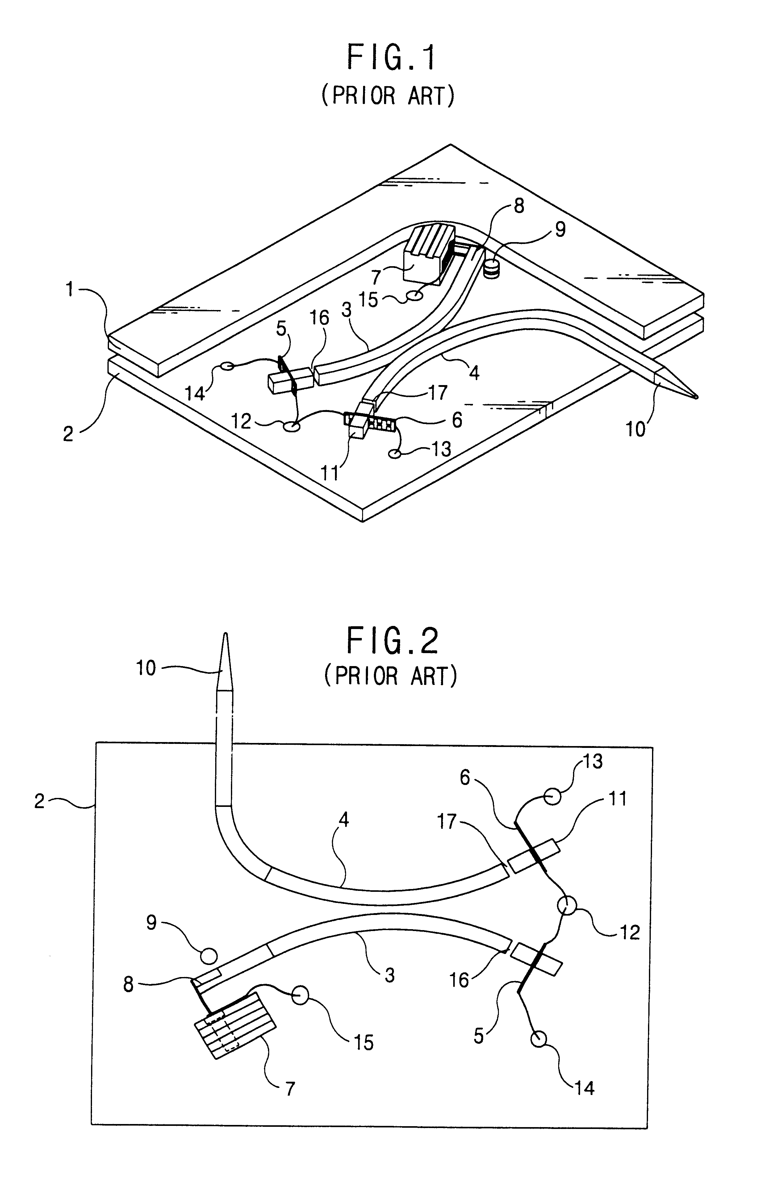
However, in fabricating the dielectric coupler having the above structure in a small size, it is not a good choice to reduce lengths of the bend dielectric lines.
Accordingly, it is inevitable to bend the dielectric lines much more, but this choice may cause a large error range in fabricating them.
A bend dielectric line may cause a transmission loss at a bending portion if the width of the dielectric line is not adaptively reduced with respect to respective bending angles corresponding frequencies.
In the fabrication, the reducing of the width without causing a large error is very difficult.
Furthermore, it is also difficult to precisely design and fabricate the bending angles, the distance between the dielectric lines and the isolation degree between ports.
However, it is difficult to precisely reduce the width of the dielectric line which is usually made of Teflon.

Method used


Image

  • Non-radiative dielectric waveguide mixer using a ring hybrid coupler
  • Non-radiative dielectric waveguide mixer using a ring hybrid coupler
  • Non-radiative dielectric waveguide mixer using a ring hybrid coupler

Examples


Embodiment Construction

Hereinafter, the present invention will be described in detail with reference to the accompanying drawings.

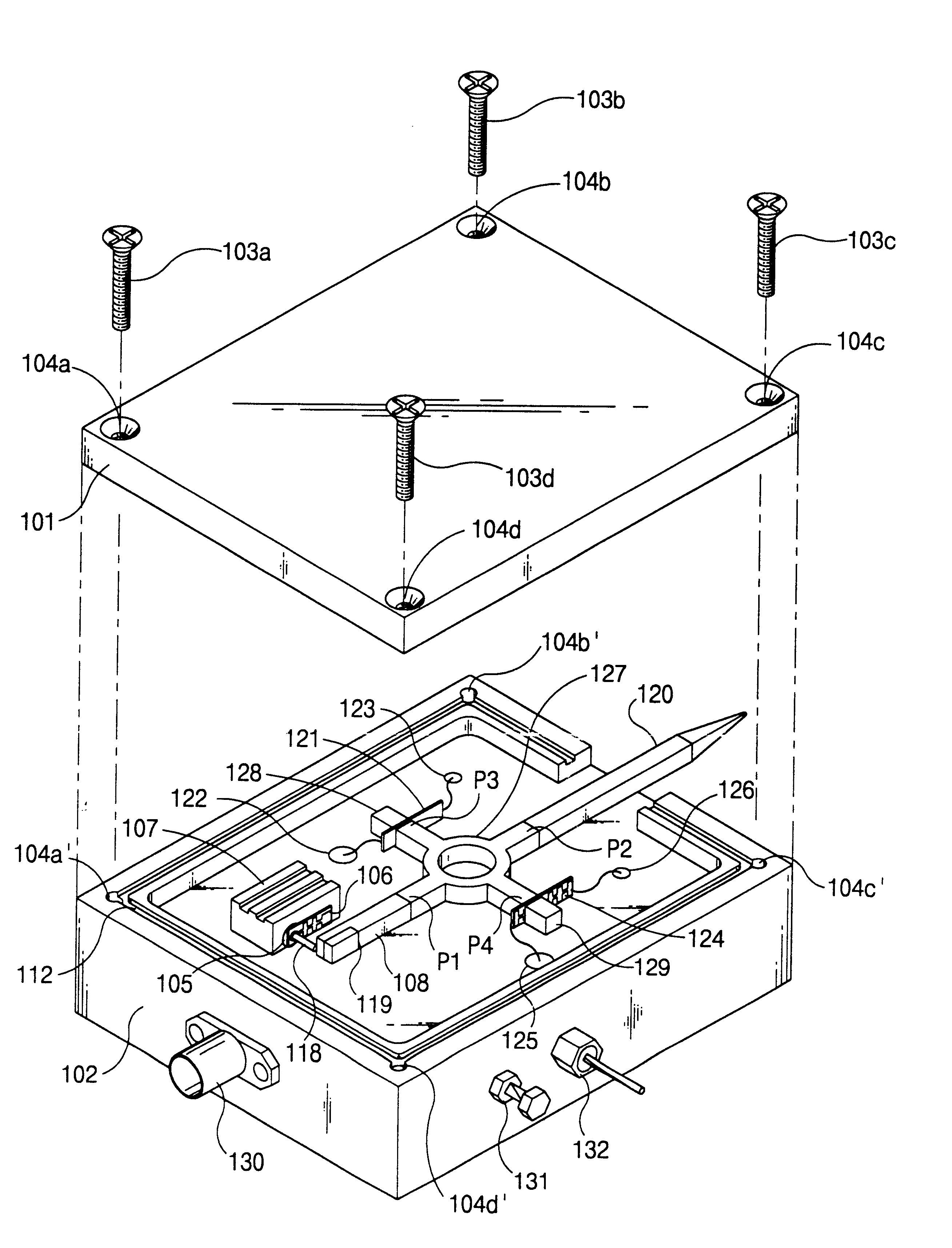
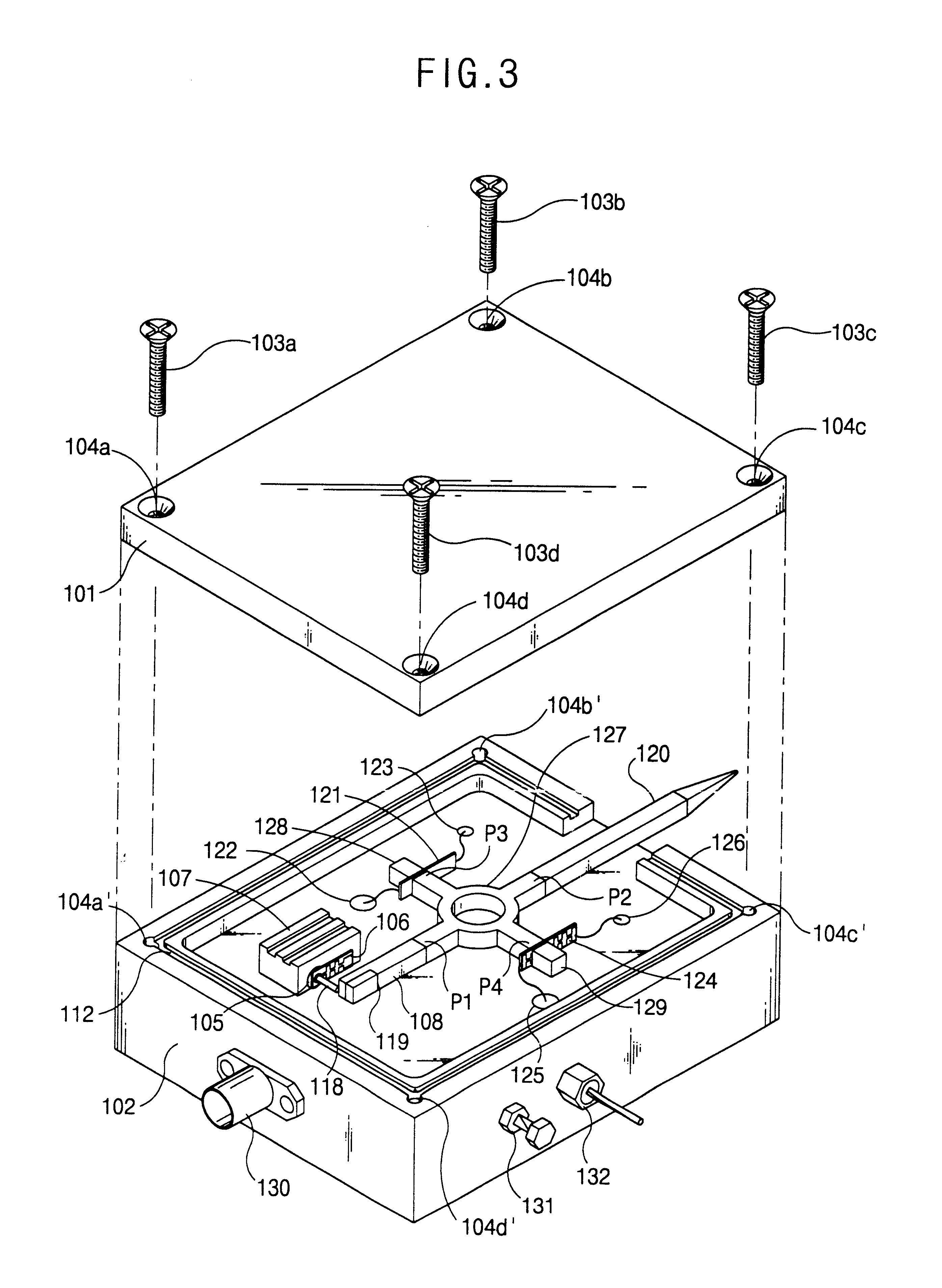
FIG. 3 shows the structure of a NRD waveguide mixer according to one embodiment of the present invention in which an upper conductive plate 101 is separated from a lower conductive plate 102. In addition, FIG. 4 shows a plan view of the NRD waveguide mixer shown in FIG. 3 in which the upper conductive plate 101 is removed.

It is one of main features of the present invention that the NRD waveguide mixer has a ring hybrid coupler 127. The ring hybrid coupler 127 includes an annular ring having a predetermined width and first to fourth ports P1, P2, P3 and P4 which radially and outwardly extend about the annular ring. The first port P1 is connected to a dielectric line 108 accommodating a mode suppressor 119 and the second port P2 is connected to a rod antenna 120 for receiving / transmitting signals. In addition, the third port P3 is connected to a dielectric line 128 by interposing...


PUM


Abstract

Disclosed is a NRD waveguide mixer adopting a ring hybrid coupler applicable to a small-sized and high functional millimeter wave receiving / transmitting device. The NRD waveguide has a housing including two parallel conductive plates. The ring hybrid coupler is installed in the housing and has an annular ring formed with first to fourth ports which are radially extended about the annular ring. An oscillating device is connected to the first port so as to generate a local oscillating signal. A rod antenna is connected to the second port so as to receive / transmit a radio frequency signal. A first balanced mixer mount is connected to the third port and is provided with a first Schottky diode. A second balanced mixer mount is connected to the fourth port and is provided with a second Schottky diode. The radio frequency signal and the oscillating signal inputted from the first and second ports are mixed in the ring hybrid coupler to be transformed into an addition signal and a subtraction signal. The addition and subtraction signals are transmitted to the third and fourth ports to switch the Schottky diodes respectively so that an intermediate signal is generated.

Description

TECHNICAL FIELD OF THE INVENTIONThe present invention relates to a non-radiative dielectric (NRD) waveguide mixer adopting a ring hybrid coupler, and more particularly, to a NRD waveguide mixer which employs a ring hybrid coupler with a simple structure utilizing a NRD waveguide and is applicable to a millimeter wave integrated circuits.BACKGROUND OF THE PRESENT INVENTIONRecently, as a mobile telecommunication system and telecommunication devices have been rapidly digitalized, it is commonly required to employ a telecommunication system having a speedy and powerful data processing capacity. Since the telecommunication system is required to process and communicate a great deal of information, its frequency band has been expanded from a microwave band to a millimeter wave band. In a wireless telecommunication system using the millimeter wavelength, it was usually manufactured as a hybrid type module. Recently, as semiconductor technology makes great strides, the wireless telecommunica...

Claims


Application Information

Patent Timeline
IPC IPC(8): H01P5/16H03D9/06H03D9/00H01P5/22
CPCH01P5/22H03D9/0641H01P5/225H01P5/222
Inventor CHOYOO, YOUNG GEUN
Owner COMOTECH CORP
Learn More