Method and apparatus for improving mounting

a technology of mounting and mounting plate, applied in the direction of mounting of support structure, modification by conduction heat transfer, instruments, etc., can solve the problems of affecting the mounting of printed board assembly and/or element, requiring very small tolerance limits, and material often creating bulges around the edges between the holes

Inactive Publication Date: 2002-05-02
TELEFON AB LM ERICSSON (PUBL)
View PDF0 Cites 7 Cited by
  • Summary
  • Abstract
  • Description
  • Claims
  • Application Information

AI Technical Summary

Problems solved by technology

If the position of a hole deviates more than 0.1 mm, the screw may not engage in a corresponding receiving thread and it may also damage the printed board assembly and / or the element as it is forced downwards by the screw machine.
The insertion of a guide pin in one of the corresponding holes in the element is often done manually and the guide pin is secured to the hole by a press fit, which demands very small limits of tolerance for the contacting surfaces of the guide pin and the wall of the hole in the element.
This coating material often create bulges around the edges between the holes for the guide pins and the surface, as well as bulges inside the holes.
Therefore, small limits of tolerance for the guide pins and the corresponding holes in the element generate higher fabrication costs than guide pins and holes with larger limits of tolerance.
Also, the manual insertion makes great demands upon a worker when inserting a guide pin, since the press fit easily gives a slight inclination from the desired guide direction of the guide pin.
The inclination might cause inaccurate positioning of the printed board assembly.
Such metal elements, such as chassis, are fabricated in advanced pre-programmed automatic machines, such as a CNC-machine, which is expensive to use and maintain.
Small details, such as protruding integrated guides on a flat surface, give a much longer, in many cases unacceptable, fabrication time in the CNC-machine.
Also, larger pieces of raw material have to be used.
Although the two above alternative procedures relates to a fastening of a printed board assembly, the same problems and disadvantages of the procedures are also true for a printed board.

Method used


Image

  • Method and apparatus for improving mounting
  • Method and apparatus for improving mounting
  • Method and apparatus for improving mounting

Examples


Embodiment Construction

[0036] While the invention covers various modifications and alternative constructions, preferred embodiments of the invention are shown in the drawings and will hereinafter be described in detail. It is to be understood, however, that the specific description and drawings are not intended to limit the invention to the specific forms disclosed. On the contrary, it is intended that the scope of the claimed invention include all modifications and alternative constructions thereof falling within the spirit and scope of the invention as expressed in the appended claims to the full range of their equivalents.

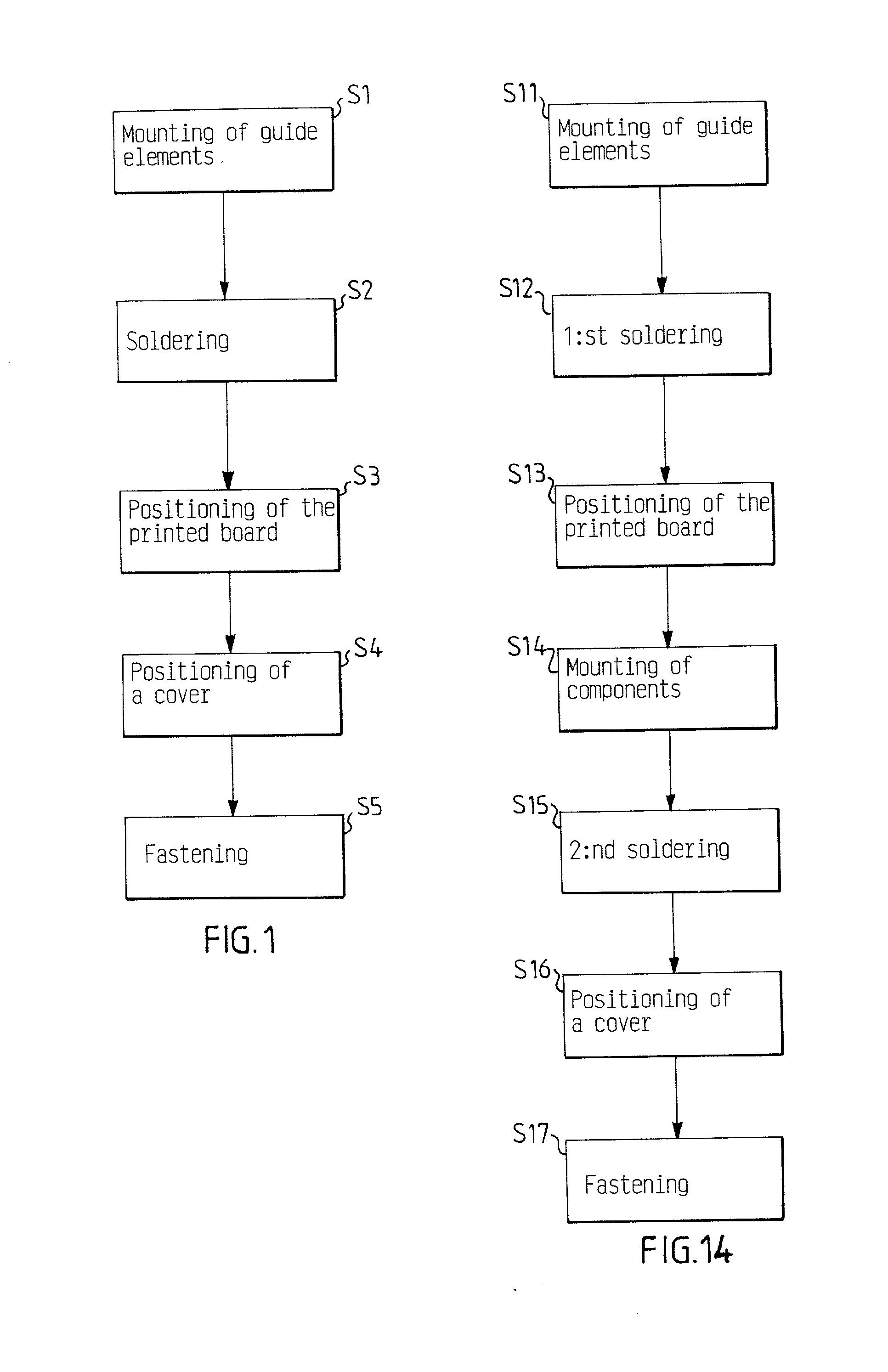
[0037] FIG. 1 shows a schematic block diagram of a preferred method for fastening a printed board to an element, where the method is divided into five principal steps S1-S5. Before the first step, a printed board 1 has been fabricated and a solder paste has been applied to at least one side of the printed board 1. Such a method is known in the prior art and is not described further.

[0...


PUM

PropertyMeasurementUnit
mechanicalaaaaaaaaaa
frusto-conical shapeaaaaaaaaaa
electric conductibilityaaaaaaaaaa

Abstract

The present invention relates to a method for fastening a printed board to an element. The method comprises the steps of: mounting at least one guide element to said printed board before said printed board is guided towards said element, fastening said at least one guide element to said printed board by soldering before said printed board is guided towards said element, and positioning said printed board on said element with the help of said at least one guide element. The invention also relates to a guide element for the method.

Description

[0001] The present invention generally relates to a method for fastening a printed board to an element and a guide element used in the method.DESCRIPTION OF RELATED ART[0002] The assembly process for an apparatus that comprises a printed board assembly involves several automatic assembly steps and often also at least some manual assembly steps. One of the assembly steps is to surface mount electronic components on a printed board. This is often done by applying a soldering paste on the printed board and automatically place the electronic components on the printed board in a so-called SMD-line by a so-called pick and place machine. After that, the electronic components are fixed to the printed board by soldering, for example in a soldering furnace. For the purpose of this patent application, the term `electronic component` is used for various electric or electronic components such as capacitors, resistors, transistors and integrated circuit chips which could be mounted on a printed b...

Claims


Application Information

Patent Timeline
Patent Type & Authority Applications(United States)
IPC IPC(8): H05K3/00H05K3/30H05K3/34H05K7/14H05K7/20
CPCH05K3/0061H05K3/308H05K3/341H05K7/1417H05K7/20509Y10T29/49117H05K2203/167Y10T29/49144Y10T29/49004Y10T29/4913H05K2201/10598
Inventor JANSSON, ULF
Owner TELEFON AB LM ERICSSON (PUBL)
Why Eureka
Try Eureka