
Pneumatic tire and method of producing the same

Inactive Publication Date: 2002-05-02
BRIDGESTONE CORP
View PDF0 Cites 11 Cited by
  • Summary
  • Abstract
  • Description
  • Claims
  • Application Information

AI Technical Summary

Benefits of technology

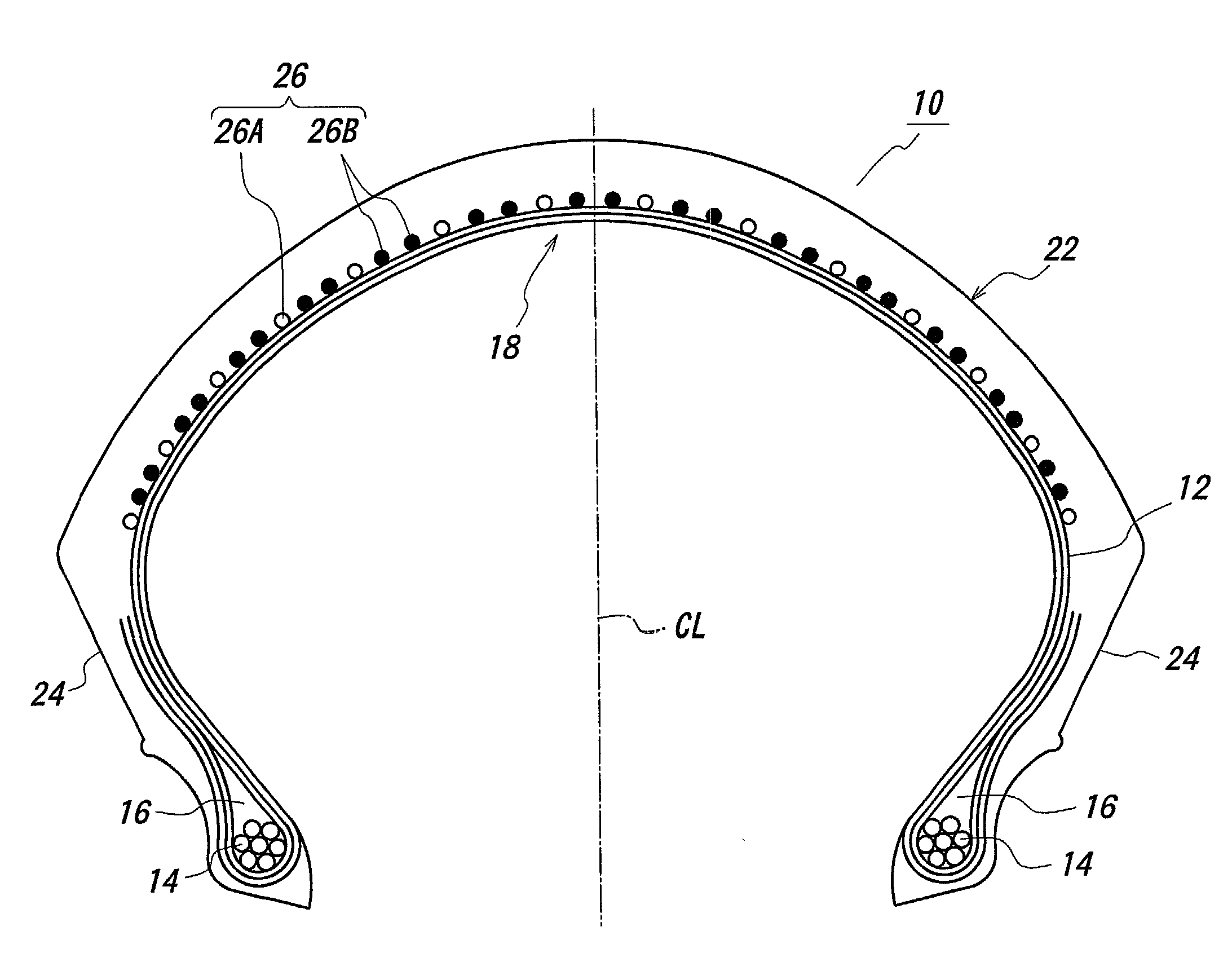
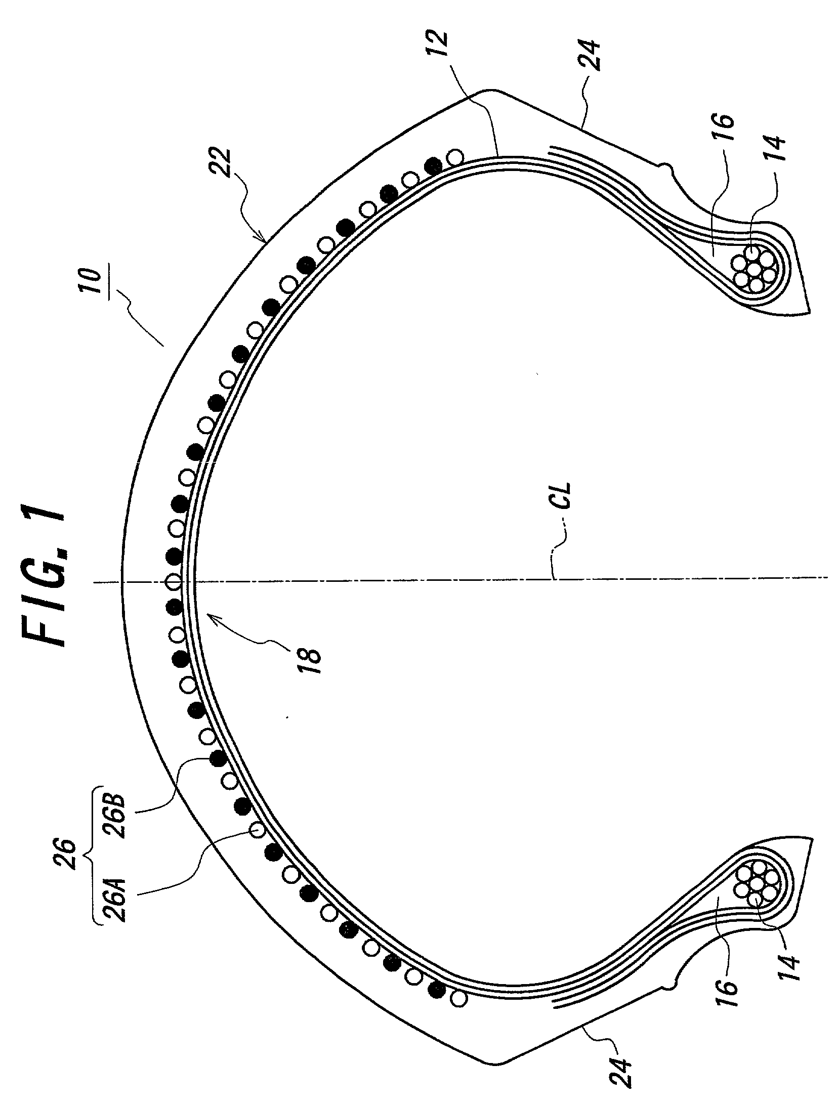
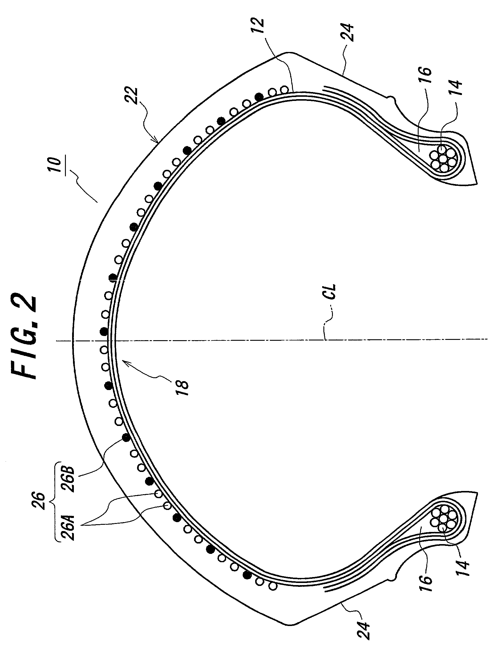
[0011] In the pneumatic tire according to the invention, the properties of the steel cord having a high compression rigidity and the properties of the fiber reinforcing cord having a low compression rigidity but a high tensile strength can effectively be utilized as a combination of such two different cords in the spiral belt, so that the guarantees of torsional rigidity in the tread, bending rigidity in a section direction, hoop strength as a belt and reinforcement effect can be attained well-balancedly.
[0012] Furthermore, it can easily be attained to not only improve the resistance to handling shimmy, high-speed stability (minimization of amplitude of wobbling and convergence of external disorder), light feeling and cornering power in the handling, gripping limit in the cornering and slippage controllability but also maintain the safety and puncture resistance under an inflation of an air pressure at a higher level.
[0013] When the spiral belt is constructed with the combination of the two different cords as mentioned above, the end count can be made to an appropriate value while providing an appropriate rigidity, whereby it is possible to improve the steering stability and other performances.
[0015] In another preferable embodiment of the first aspect, the two different cords are continuously arranged from an end of the tread to the other end thereof in a widthwise direction. In this case, the rigidity of the tread is more uniformized to more improve the performances such as durability, steering stability and the like.
[0019] In the second aspect of the invention, two different cords each having an optimum number of 1-5 can be simultaneously wound by adopting the double-start type head in the cord winding machine, in which the steel cord and the fiber-reinforcing cord are arranged from one end of the tread toward the other end thereof in the widthwise direction at once so as to always sandwich these different cords from each other and alternately position at equal intervals. As a result, the productivity of the tire is improved, and also the rigidity of the tread is made uniform by equally arranging the two different cords to improve the tire performances such as durability, steering stability and the like.

Problems solved by technology

In the spiral belt comprised of only the steel cord, the rigidity becomes too high and hence it is difficult to highly maintain the ride comfort and the slip resistance.
When the end count is merely reduced in the spiral belt comprised of only the steel cord, however, there are caused troubles such as lowering of breaking strength to air pressure, lowering of puncture resistance, lowering of fatigue resistances of the tread rubber and the carcass ply against repetitive bending due to the lowering of bending rigidity in a section direction.
In the spiral belt comprised of only the reinforcing fiber cord, the rigidity is lacking and an amplitude of shimmy behavior becomes easily large and hence it is difficult to maintain the high-speed stability at a higher level during the high-speed running and hold the light feeling and responsibility of the handling and maintain the gripping force at a higher level during the cornering and as a result, it is feared that the steering stability can not sufficiently be ensured.
However, when the end count is increased more than necessary or the other members are added, it is difficult to reduce the tire weight and also the gripping force lowers due to the lowering of shearing rigidity accompanied with the lamination.

Method used


Image

  • Pneumatic tire and method of producing the same
  • Pneumatic tire and method of producing the same
  • Pneumatic tire and method of producing the same

Examples


example 2 example 1

Hydraulic burst pressure (KPa) 250 150 250 High-speed stability 100 120 120 Light feeling and responsibility 100 120 120 Gripping force in cornering 100 110 120 Ride comfort 100 80 90

[0054] As seen from Table 1, when the tire of Example 1 is compared with the tire of Conventional Example 1, the hydraulic burst pressure is equal to and the ride comfort is somewhat low, but the other running performances are higher than those of the conventional tire. And also, the running performances in the tire of Example 1 are equal to or more than those of the tire of Conventional Example 2.

[0055] On the other hand, each of these tires is subjected to a running test by mounting onto a motorcycle as a front tire in addition to a hydraulic burst pressure test to obtain results as shown in Table 2. In this case, a radial tire comprising a circumferential belt of KEVLAR is used as a rear tire.

2 TABLE 2 Conventional Conventional Example 1 Example 2 Example 1 Example 2 Hydraulic burst 250 150 250 220 p...


PUM


Abstract

A pneumatic tire comprises a spiral belt formed by spirally winding a cord(s) along a circumferential direction of a torus tread, wherein the spiral belt is comprised of at least one layer constructed with a combination of two different cords each having an initial tension of not less than 50 cN / cord.

Description

[0001] 1. Field of the Invention[0002] This invention relates to a pneumatic tire having an improved steering stability and a method of producing such a pneumatic tire, and more particularly to a front tire and a rear tire for a motorcycle and a method of producing the same.[0003] 2. Description of Related Art[0004] In the conventional front and rear tires as a tire for a motorcycle or the like, a spiral belt formed by spirally winding a cord(s) on an outer circumference of a carcass is recently used as a belt structure. In this case, the belt is constructed by one kind of the cord. In general, there are known a spiral belt comprised of only a steel cord, a spiral belt comprised of only a reinforcing fiber cord made of a resin material or the like.[0005] In the spiral belt comprised of only the steel cord, the rigidity becomes too high and hence it is difficult to highly maintain the ride comfort and the slip resistance. For this end, it is attempted to reduce an end count as the wi...

Claims


Application Information

Patent Timeline
IPC IPC(8): B29D30/70B60C9/20B60C9/00B60C9/18B60C9/22
CPCB60C9/2204B29D30/1628Y10T152/10783B60C2009/2029B29D30/70B60C2200/10B60C2009/2209
Inventor NAKAMURA, TSUTOMU
Owner BRIDGESTONE CORP
Learn More