
Noise reduction sandwich panel, notably for aircraft turbojet engine

a technology of aircraft turbojet engines and sandwich panels, applied in the direction of efficient propulsion technologies, machines/engines, instruments, etc., can solve the problems of complex production of linear one-degree of freedom sandwich panels, limited frequency range damped by such structures, and low erosion resistance, etc., to achieve the effect of easy and quick production

Inactive Publication Date: 2002-05-02
AIRBUS OPERATIONS (SAS)
View PDF0 Cites 29 Cited by
  • Summary
  • Abstract
  • Description
  • Claims
  • Application Information

AI Technical Summary

Benefits of technology

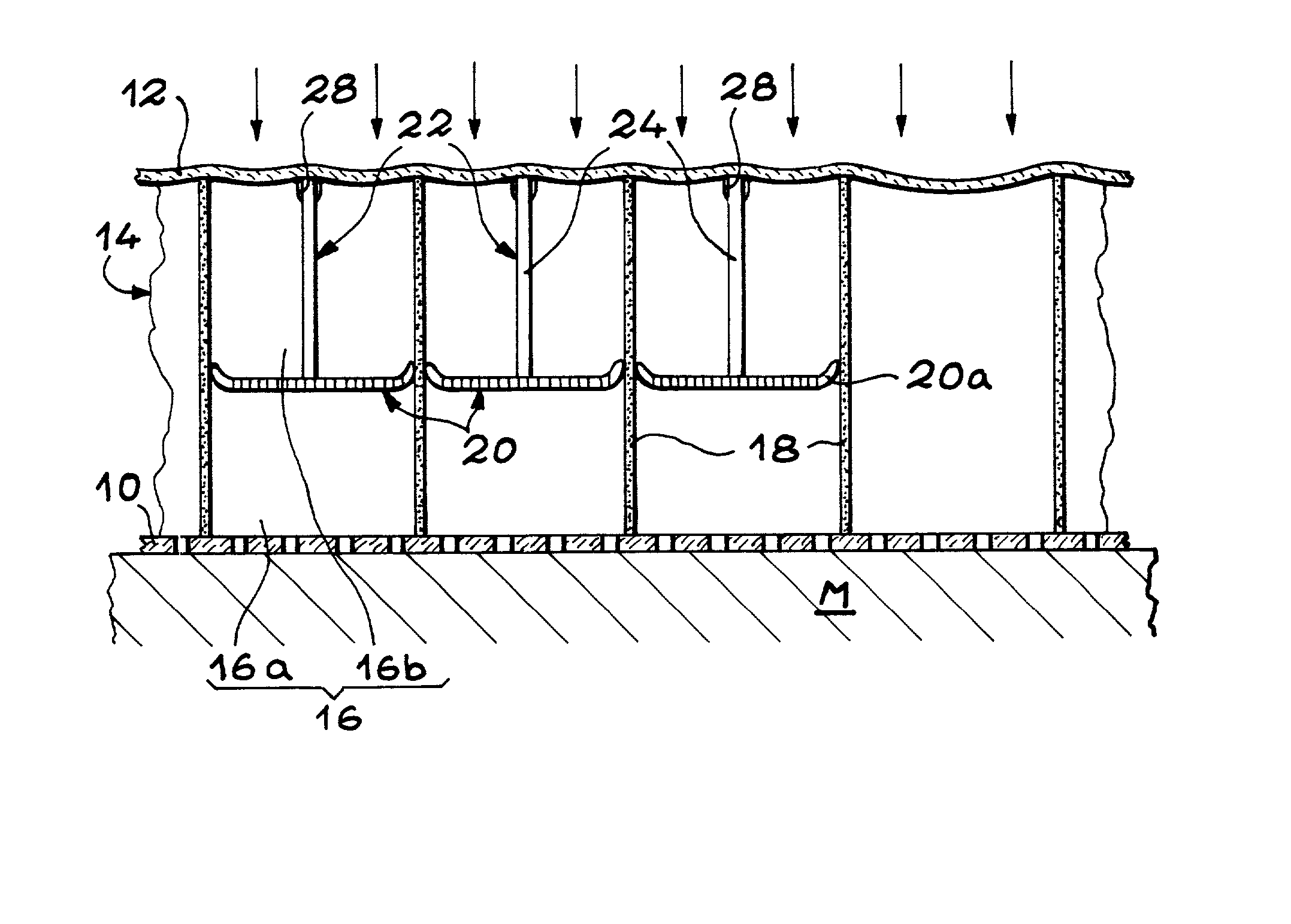
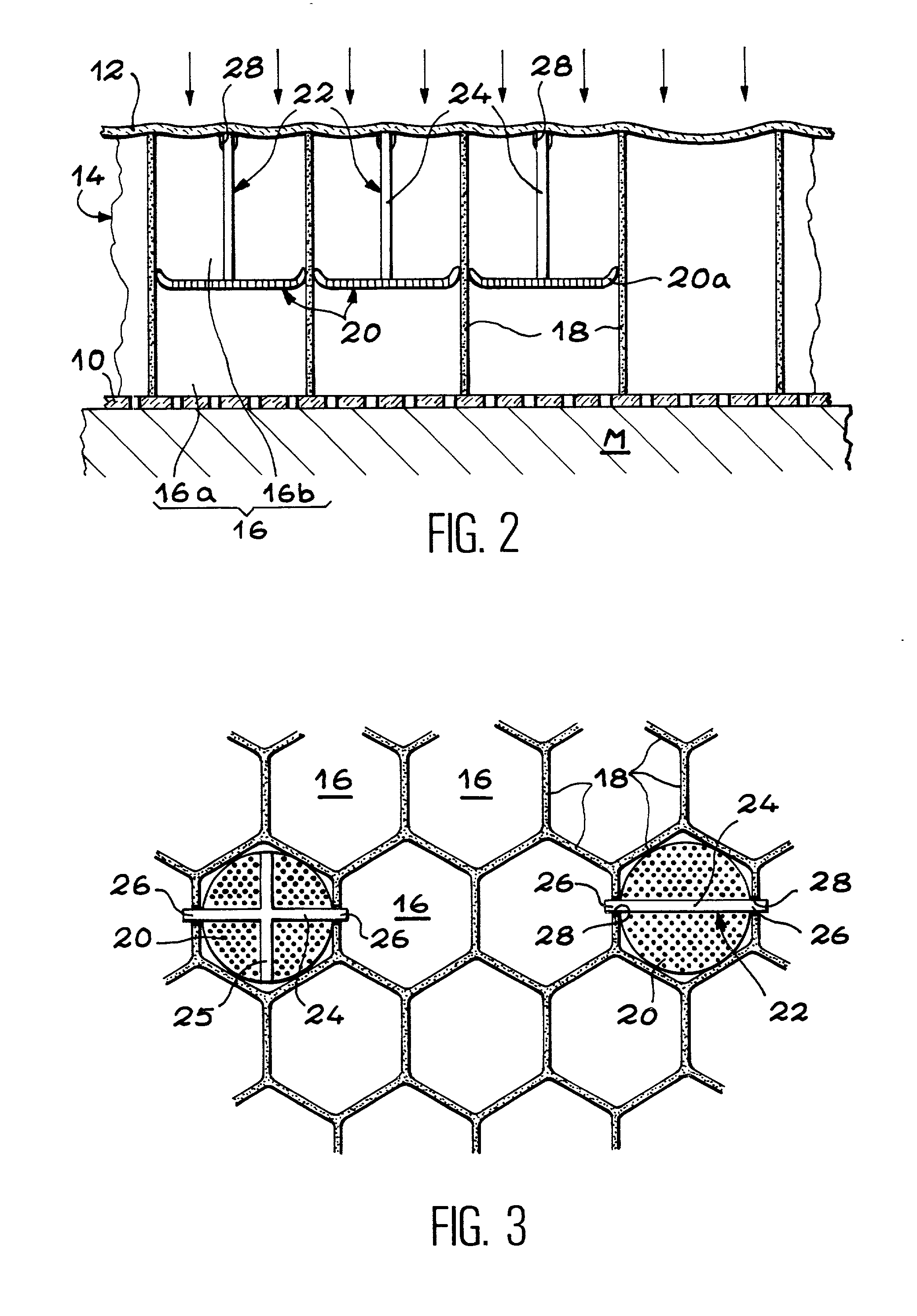
[0031] Advantageously, the separative components have the shape of substantially planar disks. The external peripheral of each of the separative components may then be raised towards the reflectors or towards the resistive layer, to further facilitate the mounting.
[0036] According to a second embodiment of the invention, each positioning unit supports several separative components, inserted in aligned cells along a given direction, and integrates, between each pair of consecutive separative components which it supports, at least one tab able to deform along said direction. With this layout, the separative components may be placed easily and quickly, in spite of the possible variations in the pitch of the aligned cells resulting from manufacturing tolerances and from the optional non-planarity of the panel.

Problems solved by technology

Further, as the frequency damped by each cell depends on its depth and as all the cells of the panel have the same depth, the range of frequencies damped by such a structure is limited.
In addition, as the resistive layer is in a composite material, the structure has low erosion resistance.
However, the production of a linear one-degree-of-freedom sandwich panel is more complicated than that of non-linear one-degree-of-freedom panel, because the resistive layer comprises two constituents.
If the components or the assembly methods are not under control, the structure may have areas of acoustical non-homogeneity and there are also risks of delamination of the resistive layer.
Further, risks of corrosion of the resistive layer impose an additional constraint as to the choice of the materials used.
Finally, the assembly method of such a panel is lengthy and costly.
However, areas of acoustical non-homogeneity appear because of misalignment of the cells from both waffle cores which inevitably occurs upon forming the panel.
Finally, the assembly method for a panel of this type is lengthy and costly, as the different components of the structure must be assembled one by one.
However, the problem of accurately placing the different pieces, repeatedly and reliably, is not solved in this document.
However, this method is relatively lengthy and delicate to implement and may prove to be dangerous because of the use of a liquid such as mercury.
Further, it is completely unsuitable in the case of a non-planar sandwich panel.
However, the implementation of the various techniques described in document GB-A-1,463,918, practically gives rise to practically insurmountable difficulties.
Indeed, the implementation of the separative components described in this document would be practically impossible because of the variations in the sizes and shapes of the cells which inevitably occur on a sandwich panel of a large dimension and of a non-planar shape.
Thus, taking the small size of the cells into account, their partitions are relatively stiff and practically do not allow the differences in shapes and sizes to be compensated upon the placing of the described separative components, the shape and dimensions of which are the same as those of the cells.
Indeed, the proposed solutions in document GB-A1,463,918, do not allow the distance between the neighboring separative components to be varied, to take into account the manufacturing tolerances of the honeycomb structure.
Moreover, in the embodiment according to which two separative components placed in two neighboring cells are directly joined together through their adjacent edges and are supported on the upper edge of a notch cut out in the partition separating these cells, the repeated cutting out of this partition on the whole of the panel lowers the mechanical strength of the latter in such an unacceptable way.

Method used


Image

  • Noise reduction sandwich panel, notably for aircraft turbojet engine
  • Noise reduction sandwich panel, notably for aircraft turbojet engine
  • Noise reduction sandwich panel, notably for aircraft turbojet engine

Examples


first embodiment

[0032] According to the invention, each positioning unit then supports only one separative component.

[0033] Each positioning unit may then comprise a small plate, placed between the separative component which it supports and the reflector or the resistive layer, substantially perpendicularly to the latter, said small plate comprising two protruding portions, adjacent to the reflector or to the resistive layer, which are supported in the notches formed in the edges adjacent to the reflector and to the resistive layer of both opposite partitions of the corresponding cells.

[0034] Alternatively, each positioning unit may also comprise at least two tabs which extend between the separative component which they support and the reflector or the resistive layer, each tab comprising an end folded between the waffle core and the reflector or the resistive layer.

[0035] In this case, advantageously, at least one of the tabs completely crosses a cell adjacent to the one which contains the separat...

second embodiment

[0036] According to the invention, each positioning unit supports several separative components, inserted in aligned cells along a given direction, and integrates, between each pair of consecutive separative components which it supports, at least one tab able to deform along said direction. With this layout, the separative components may be placed easily and quickly, in spite of the possible variations in the pitch of the aligned cells resulting from manufacturing tolerances and from the optional non-planarity of the panel.

[0037] In this embodiment, the separative components supported by a same position unit, are advantageously placed in every other cell, in the direction of the alignment of the cells.

[0038] In this case, each positioning unit may comprise small plates, each of which is placed between the reflector and the resistive layer and one of the separative components supported by this positioning unit, perpendicularly to the reflector or to the resistive layer. A tab then jo...


PUM


Abstract

Noise reduction sandwich panel, notably for an aircraft turbojet engine. In order to produce a noise reduction sandwich panel having a structure with two degrees of freedom, inserted separative components (20) are placed into the hexagonal cells (16) of the unique waffle core of the panel. More specifically, the separative components (20) have an substantially circular external peripheral edge, which allows them to be easily assembled, in spite of the deformations of the walls (18) of the cells (16) due to manufacturing tolerances and to the optional forming of the waffle core. Advantageously, several separative components (20) are supported by a same positioning unit (22), which then allows relative displacement between the separative components.

Description

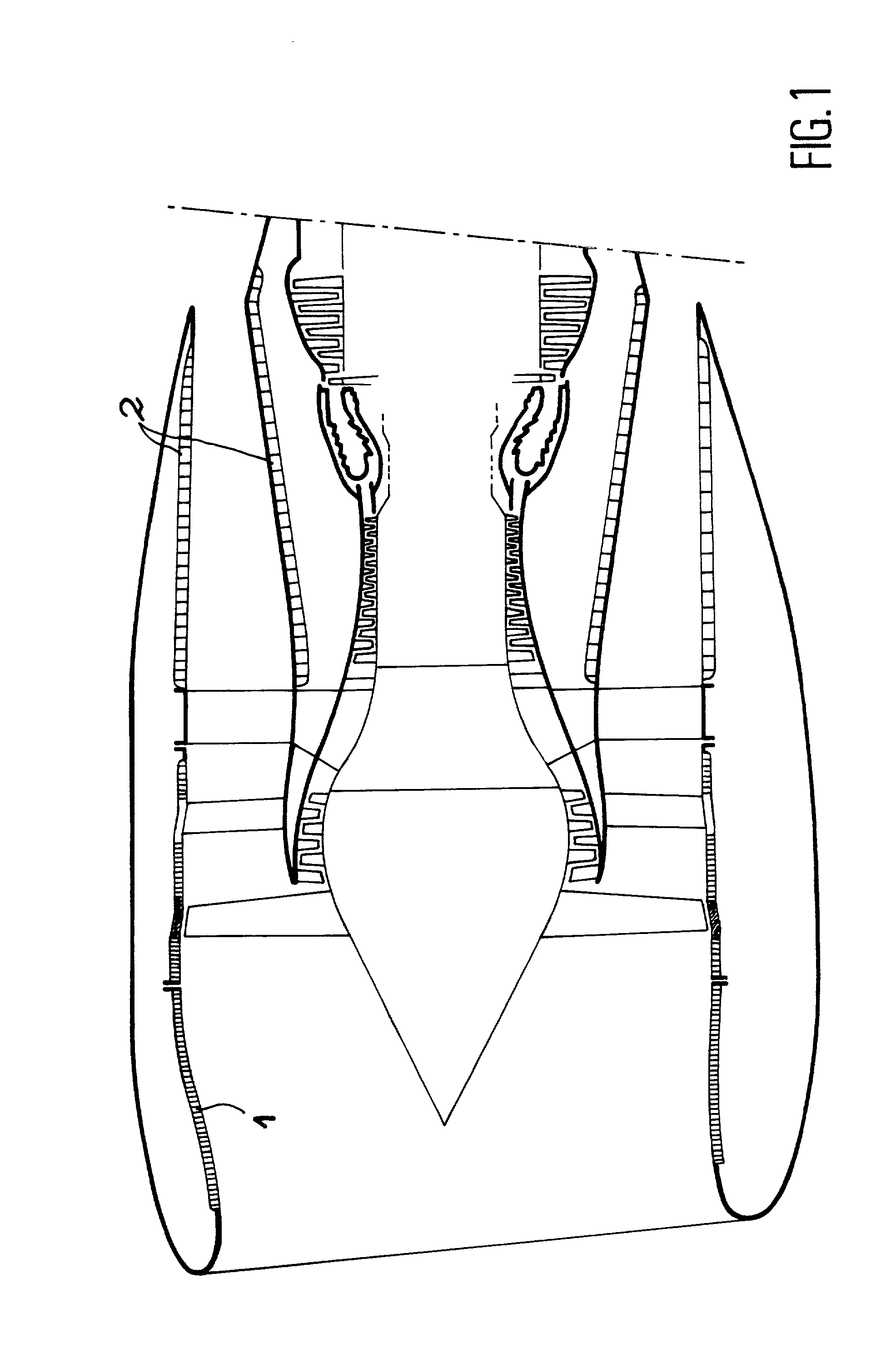
[0001] The invention relates to a noise reduction sandwich panel of the type including a waffle core mounted between a porous resistive layer and a reflector.[0002] Such a sandwich panel may advantageously be used in an aircraft turbojet engine, for example in order to form the internal wall of the air intake and of the thrust reverser.STATE OF THE ART[0003] In aircraft turbojet engines developed during the last couple of years, noise reduction is one of the priority goals. Indeed, present regulations relative to noise level around airports impose a threshold not to be exceeded. Beyond this threshold, airlines are under obligation to pay financial penalties to the airport authorities.[0004] For this purpose and as FIG. 1 of the appended drawings illustrates this in a sectional view and very schematically, it is common practice to produce the major portion of the inner wall 1 of the air intake of a turbojet engine, as well as the walls 2 of the thrust reverser as noise reduction sand...

Claims


Application Information

Patent Timeline
IPC IPC(8): B32B3/12E04C2/36F02C7/045F02K1/82G10K11/172
CPCB32B3/12E04C2/365F02C7/045F05D2260/96G10K11/172Y02T50/672F02K1/827Y02T50/60
Inventor PORTE, ALAINBATARD, HERVE
Owner AIRBUS OPERATIONS (SAS)
Learn More