Magnetic field measurement apparatus
a technology of magnetic field and shielding apparatus, which is applied in the direction of magnetic field measurement using superconductive devices, instruments, applications, etc., can solve the problems of heavy shielded room, and high cost of magnetic shield
- Summary
- Abstract
- Description
- Claims
- Application Information
AI Technical Summary
Benefits of technology
Problems solved by technology
Method used
Image
Examples
first embodiment
[0097] (First Embodiment)
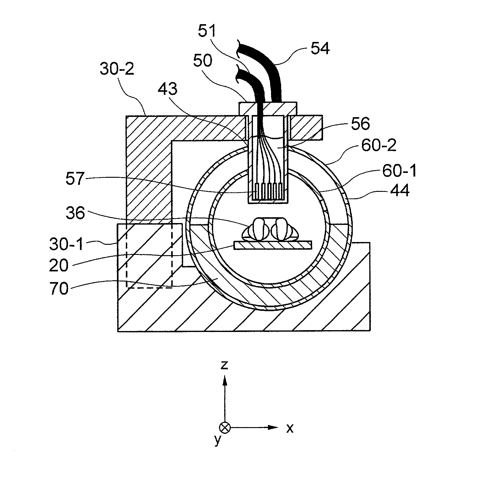
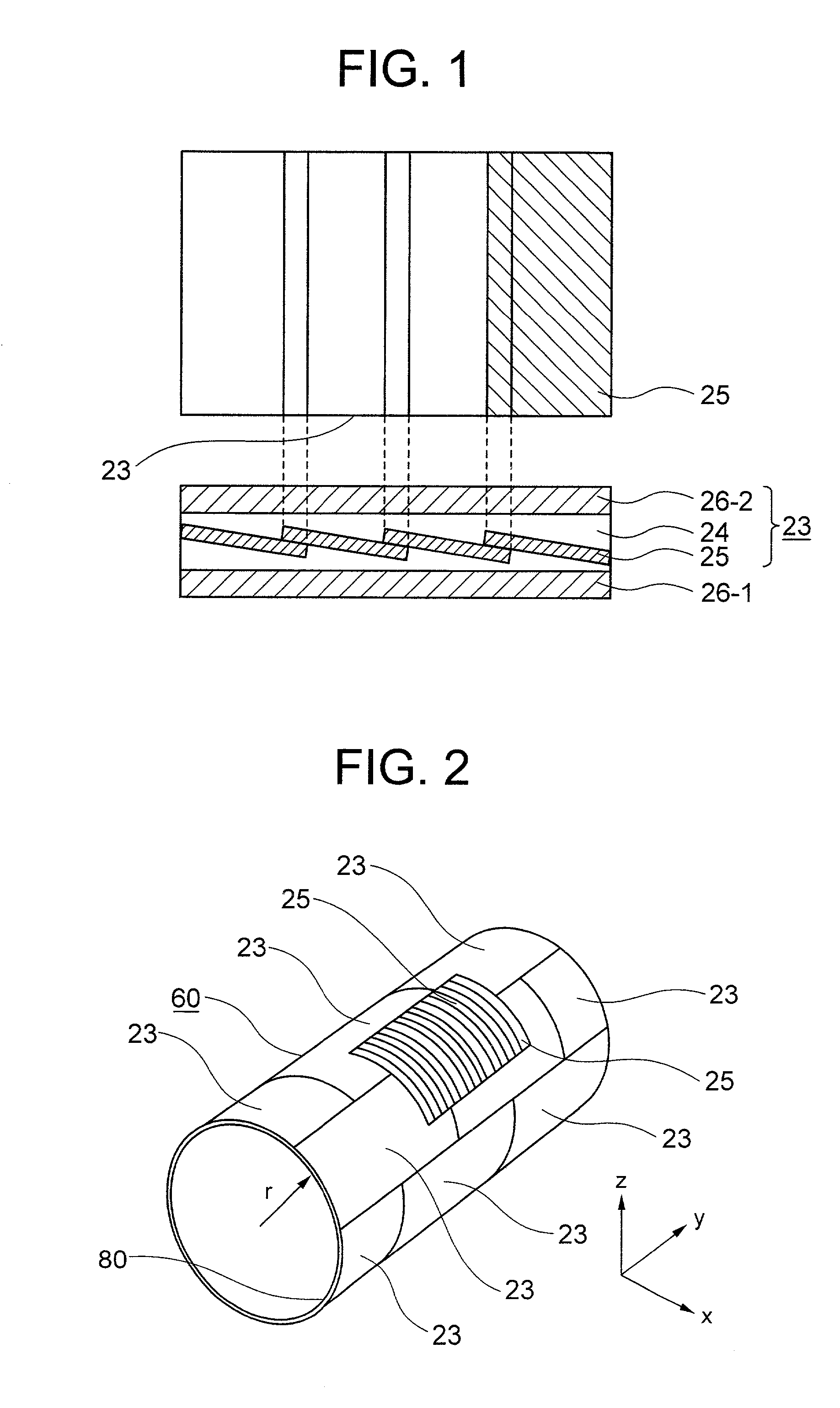
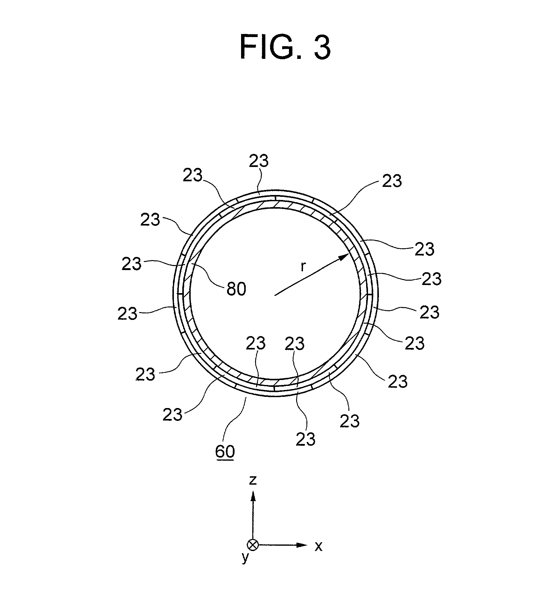
[0098] FIG. 4 is a perspective view for illustrating the configuration example of the biomagnetic field measuring apparatus in a first embodiment of the present invention. FIG. 5 is a perspective view for illustrating the magnetic field shielding apparatus 40 illustrated in FIG. 4. FIG. 6 is a cross-sectional view of the biomagnetic field measuring apparatus illustrated in FIG. 4 in a plane passing through the center of its measuring field-of-view.
[0099] The biomagnetic field measuring apparatus includes the following components: The magnetic field shielding apparatus 40, the cryostat 50 for maintaining the plurality of SQUID magnetic-flux meters 57 at a low-temperature, the plurality of SQUID magnetic-flux meters 57 detecting the magnetic field (the biomagnetic field) generated from the examination-target (the living body), a gantry 30-2 for supporting the cryostat 50, a magnetic field shielding apparatus / gantry supporting base 30-1 for supporting the magne...
second embodiment
[0112] (Second Embodiment)
[0113] FIG. 7 is a perspective view for illustrating the configuration example of the biomagnetic field measuring apparatus in a second embodiment of the present invention. FIG. 8 is a perspective view for illustrating the magnetic field shielding apparatus illustrated in FIG. 7. FIG. 9 is a cross-sectional view of the biomagnetic field measuring apparatus illustrated in FIG. 7 in a plane passing through the center of its measuring field-of-view, including a partially enlarged cross-section of the measuring apparatus.
[0114] Hereinafter, the explanation will be given mainly concerning the points differing from those in the first embodiment. In the configuration of the biomagnetic field measuring apparatus in the second embodiment, the magnetic field shielding apparatus 40 explained in the first embodiment is divided into 2 portions in the y direction, thereby being configured by a first portion 40-1 of the magnetic field shielding apparatus and a second port...
third embodiment
[0125] (Third Embodiment)
[0126] FIG. 10 is a perspective view for illustrating the configuration example of the biomagnetic field measuring apparatus in a third embodiment of the present invention. FIG. 11 is a perspective view for illustrating the magnetic field shielding apparatus illustrated in FIG. 10, including a partially enlarged cross-section of the shielding apparatus. FIG. 12 is a cross-sectional view for explaining the putting in-and-out of the examination-target (i.e., the patient) toward the biomagnetic field measuring apparatus illustrated in FIG. 7, including a partially enlarged cross-section of the measuring apparatus.
[0127] Hereinafter, the explanation will be given mainly concerning the points differing from those in the first embodiment. The magnetic field shielding apparatus 40 explained in the first embodiment is divided into 2 portions in the circumferential direction, thereby being configured by a first portion 40-3 of the magnetic field shielding apparatus a...
PUM
 Abstract
Description
Claims
Application Information
 - R&D
- Intellectual Property
- Life Sciences
- Materials
- Tech Scout
- Unparalleled Data Quality
- Higher Quality Content
- 60% Fewer Hallucinations
Browse by: Latest US Patents, China's latest patents, Technical Efficacy Thesaurus, Application Domain, Technology Topic, Popular Technical Reports.
© 2025 PatSnap. All rights reserved.Legal|Privacy policy|Modern Slavery Act Transparency Statement|Sitemap|About US| Contact US: help@patsnap.com


