Linear medium pulling and retrieval system

a technology of pulling and retrieval system and linear medium, which is applied in the direction of cables, instruments, weapons, etc., can solve the problems of not being able to find teaching, patents do not disclose or claim specific "drag lines", and achieve the effect of facilitating left and right-hand users/operation

Inactive Publication Date: 2002-05-09
HALO PRODS
View PDF0 Cites 21 Cited by
  • Summary
  • Abstract
  • Description
  • Claims
  • Application Information

AI Technical Summary

Benefits of technology

0023] which is ambidextrous whereby selected housing d

Problems solved by technology

Even in the most recent inventions one can find no evidence that the inventors have considered and/or properly applied the principles of mechanics and aerodynamics.
The patent does not disclose or claim any specific "drag line" or coil-holder, spool or reel or method for holding and/or releasing the "

Method used


Image

  • Linear medium pulling and retrieval system
  • Linear medium pulling and retrieval system
  • Linear medium pulling and retrieval system

Examples


Embodiment Construction

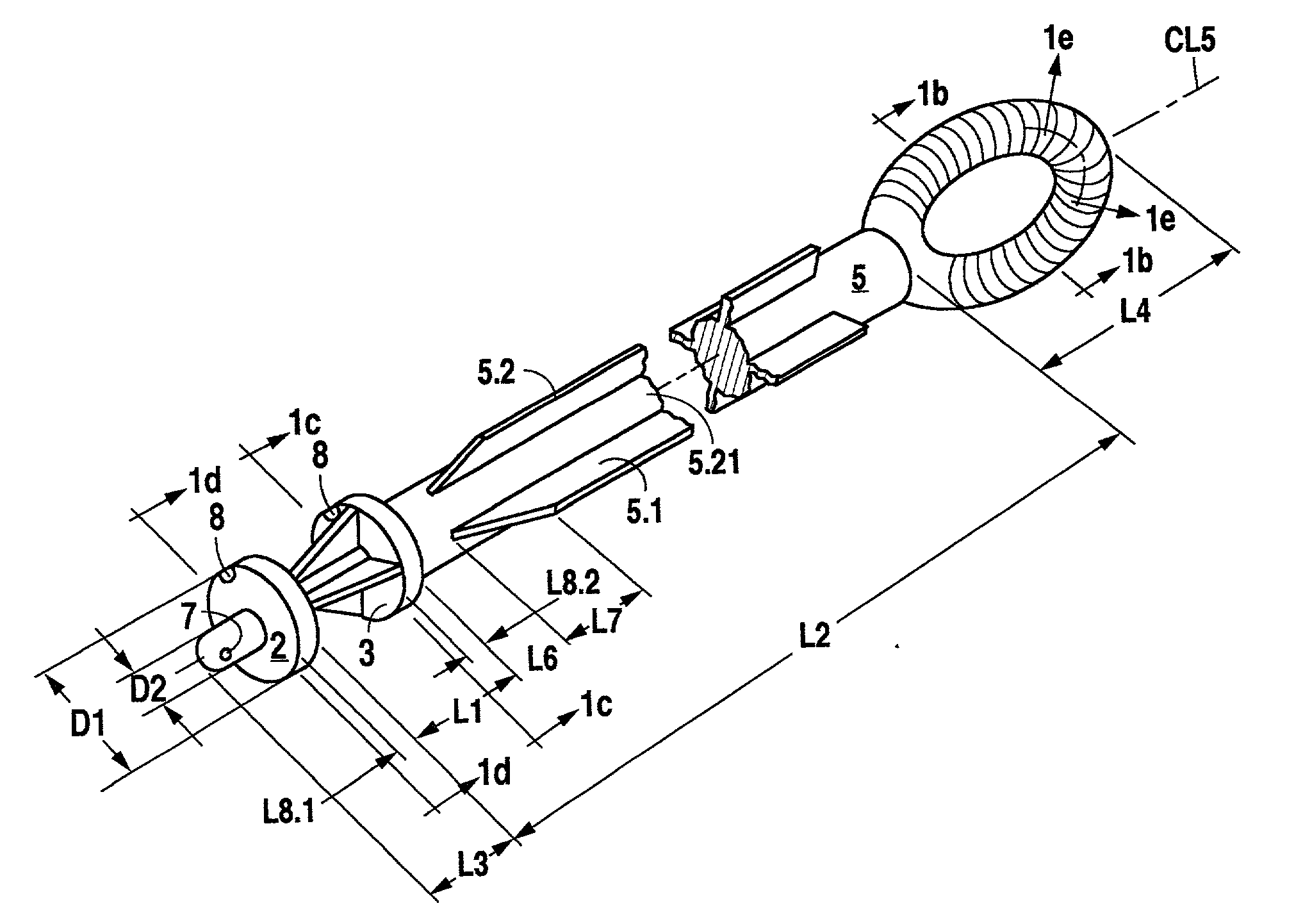
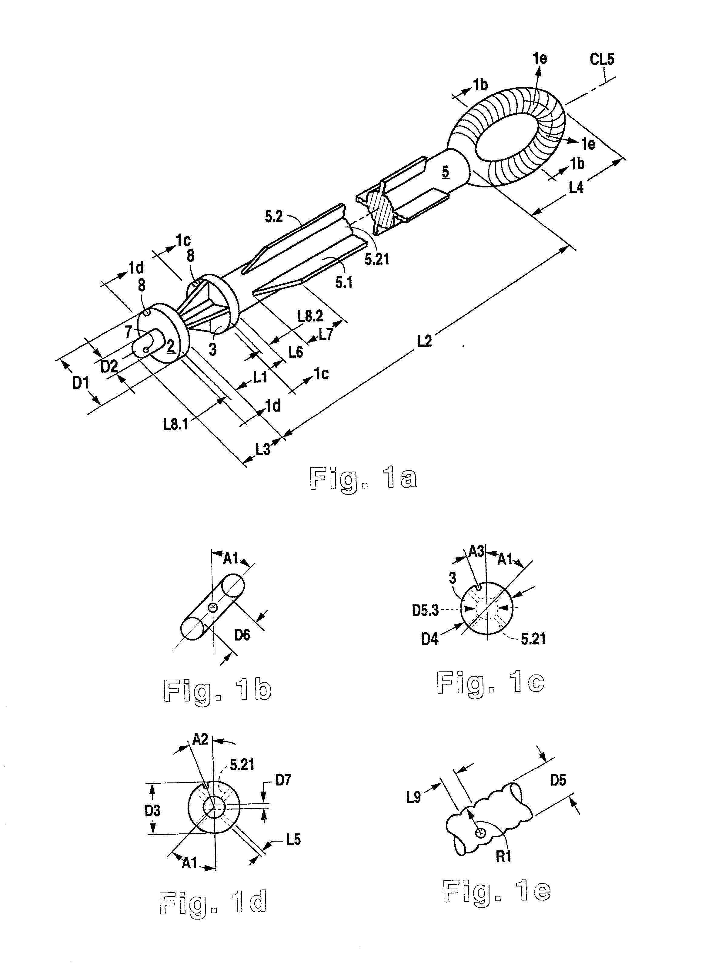
[0062] Table 1 gives a complete listing of the indicia and definitions of special nomenclature used herein. For many parameters, the typical value and the usual range, in the units indicated, is given. For the present invention, the optimal dimensions and radial clearances can be conveniently scaled by the free OD of the ESE (energy storage element) or compression spring. The length scaling factors shown in the right column therefore indicate the ratio of the specific length or distance value to the value of D30.3, i.e., the scaled value of D30.3 is exactly 1.00. This sizing approach makes it possible to prepare alternative mechanically-related smaller or larger designs with different power and range without departing from the basic-concept parameters of the present invention. Alternative specific pivot axis positions are designated by specific polar coordinates measured from the a reference point defined by the intersection of (a) the axis of the contact circle defined by the proje...


PUM


Abstract

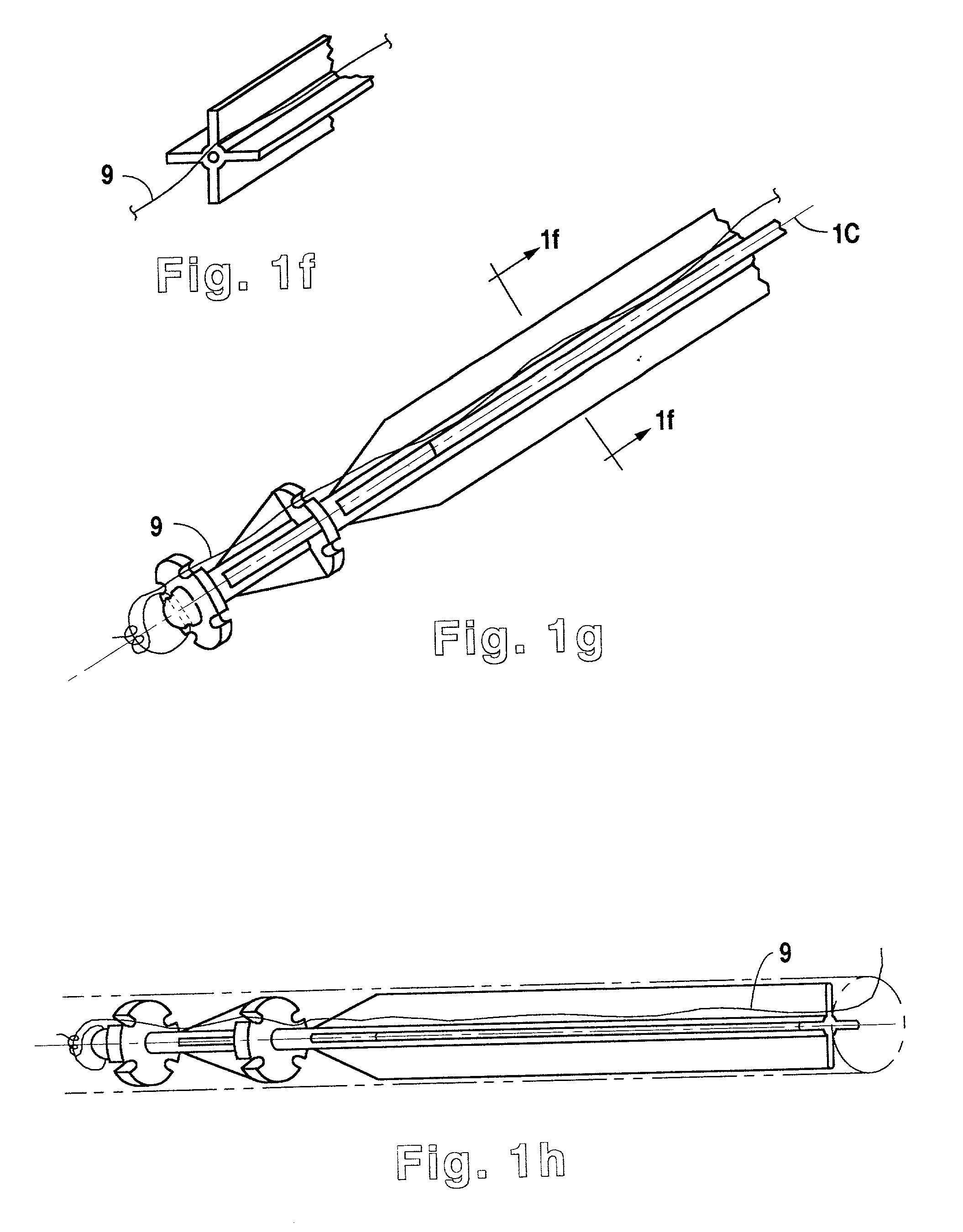
A generalized, rationally-scaled design is disclosed for a line laying system for use in stringing communications cable across inaccessible spaces. The system includes a tethered projectile which is accurately aimed and launched to a defined target zone by means of a energy-store coupled with a pivoting release lever. The geometric details of placement of the pivot axis of the release lever are disclosed in detail. Specific configurations of the projectile guides and spring support ribs are also disclosed. Implications of design and materials upon accuracy and range are considered and optimal component finishes and tolerances are indicated.

Description

CROSS-REFERENCE TO RELATED INVENTIONS[0001] This is a CIP application filed during the pendancy in USPTO of U.S. Utility App: 09 / 432327; it claims the priority of the following applications:[0002] U.S. Provisional App: 60 / 111573, Filed: Dec. 9, 1998[0003] U.S. Utility App: 09 / 432327, filed Nov. 2, 1999[0004] PCT / US99 / 29328, int. filing date Dec. 9, 1999 and related foreign filings in DE and GB[0005] This invention relates to a device which enables a mechanic or technician, using an affixed sighting mechanism, to project or "shoot" a small rigid or semi-rigid mechanism or clamping fixture, which is attached to a tether and source of line accurately through a predetermined path towards a source of wire, fiber-optic medium, cabling, or tubing, allowing attachment of such tubing to the clamping fixture and retraction of medium back to the original point of projection.[0006] One of the most difficult and undesirable, potentially hazardous, and labor intensive tasks encountered by the ele...

Claims


Application Information

Patent Timeline
IPC IPC(8): B63C9/26F41B7/00F42B12/68G02B6/44G02B6/50H02G1/08
CPCB63C9/26F41B7/00F42B12/68H02G1/085G02B6/502H02G1/081G02B6/4465G02B6/545
Inventor HAYES, ROGER D.FORSBERG, FRANCIS C.
Owner HALO PRODS
Why Eureka
Try Eureka