Laser Beam Device With Apertured or Non-Apertured Reflective Element

a laser beam and reflective element technology, applied in the direction of reference lines/planes/sectors, angle measurement, instruments, etc., can solve the problems of increased cost, complexity, and additional beams, and achieve the effect of simple, stable and cost effective laser devices

Inactive Publication Date: 2002-05-09
ROBERT BOSCH CO LTD
View PDF0 Cites 17 Cited by
  • Summary
  • Abstract
  • Description
  • Claims
  • Application Information

AI Technical Summary

Benefits of technology

0005] The present invention relates to improvements to this field rendering simpler, more stable and cost effecti

Problems solved by technology

More beams require more mirrors

Method used


Image

  • Laser Beam Device With Apertured or Non-Apertured Reflective Element
  • Laser Beam Device With Apertured or Non-Apertured Reflective Element
  • Laser Beam Device With Apertured or Non-Apertured Reflective Element

Examples


Embodiment Construction

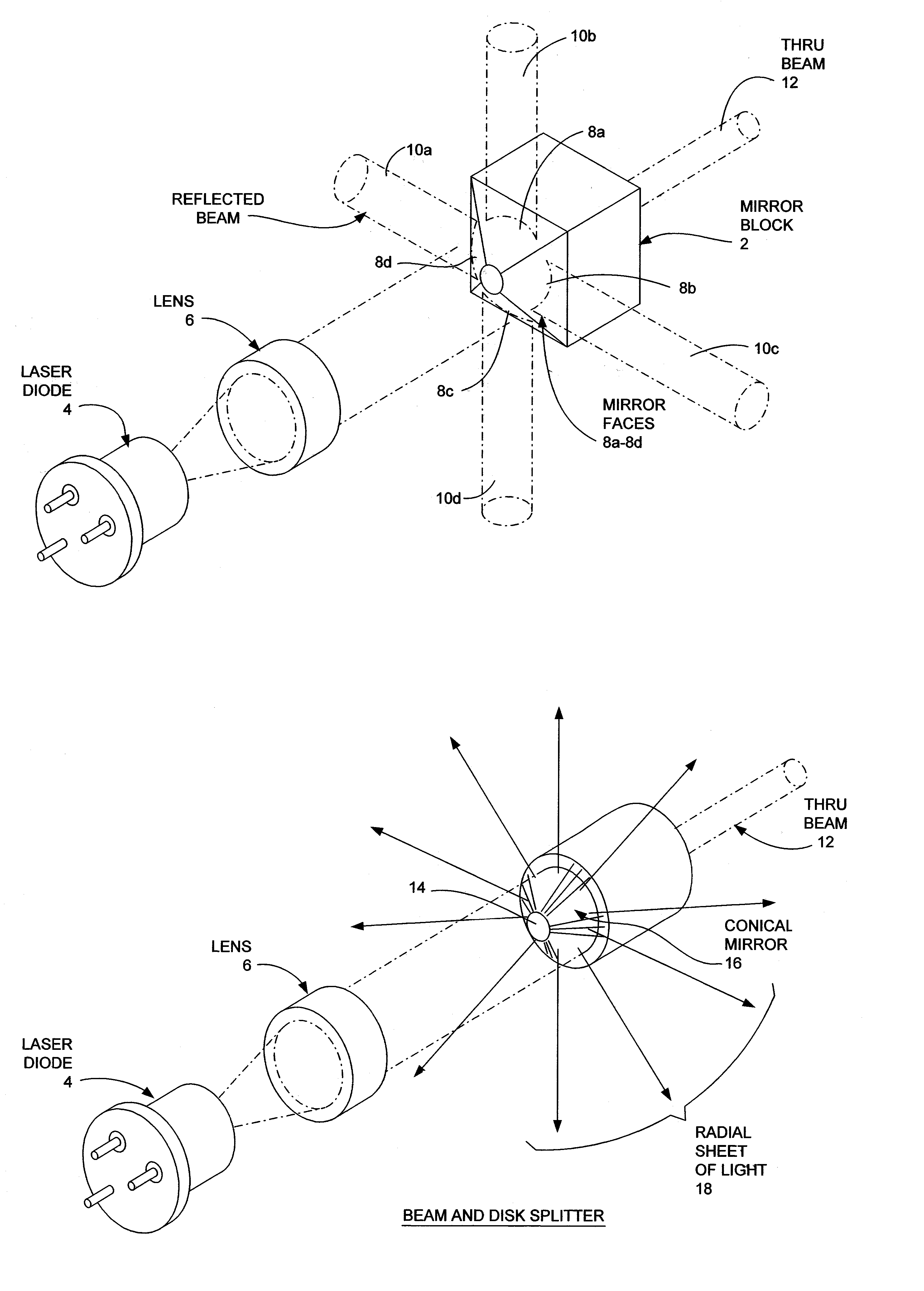
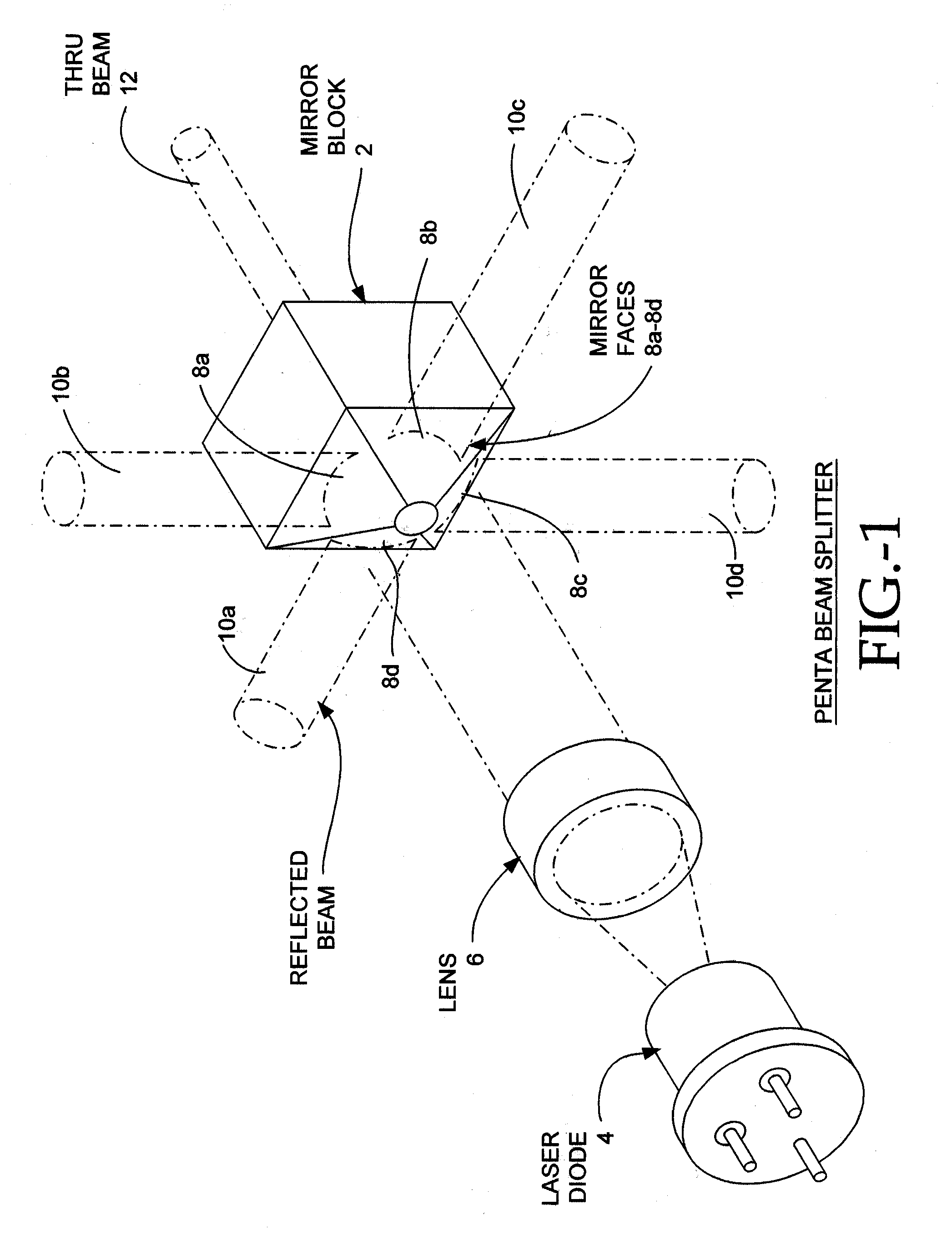
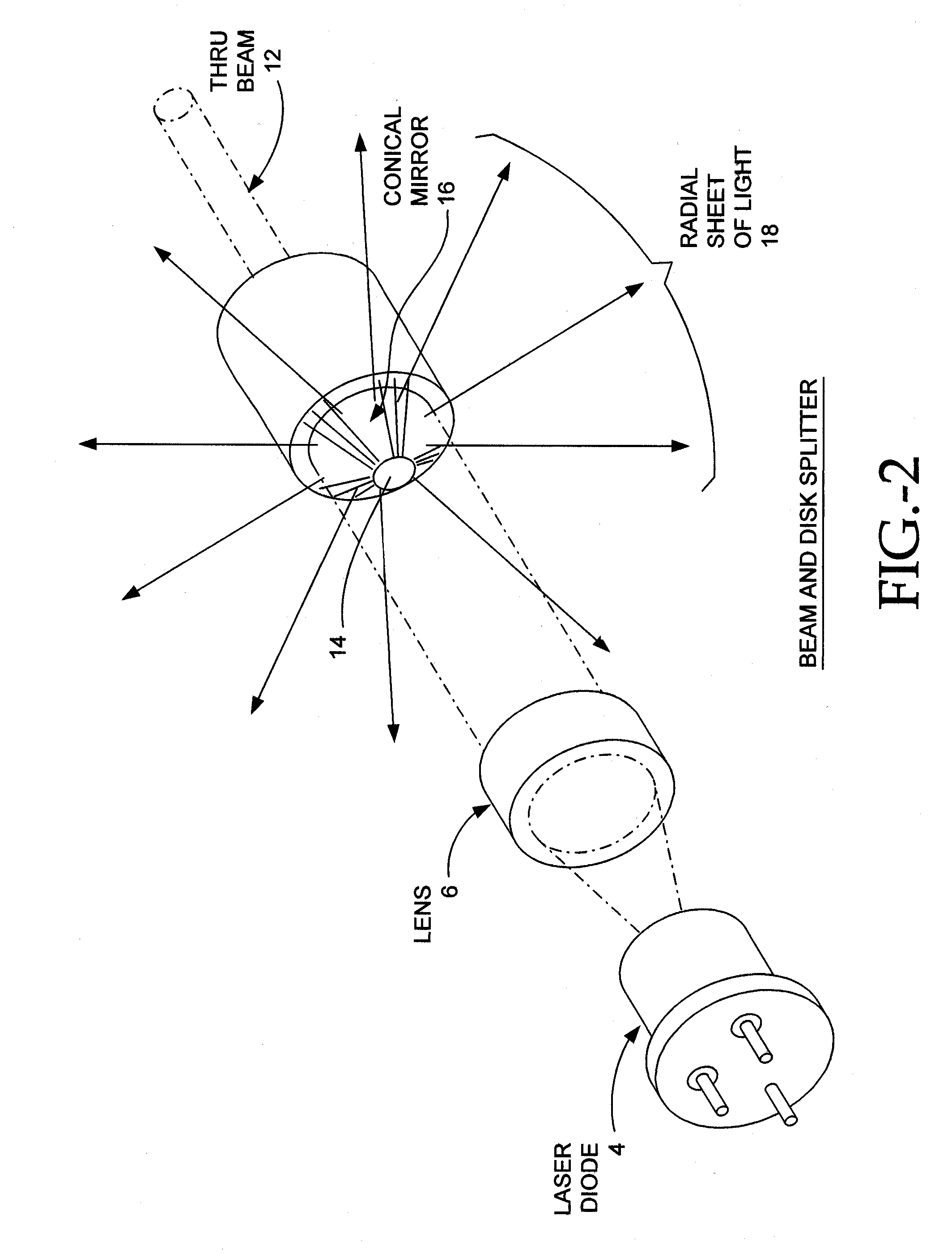
[0020] I. Penta Beam Splitter

[0021] The present invention (Fig. 1) achieves the much-desired feature of producing a series of mutually orthogonal beams with a single splitter. Further, the beams are mutually coincident, that is, the beams all emanate from the same point.

[0022] The splitter in this embodiment is fabricated from a small block or cylinder of aluminum 2. Other materials and fabrication techniques can be otherwise employed. Four reflective mirror surfaces 8a-8d are produced by a process known as "single point diamond turning". This process is widely used to produce polygonal mirrors for laser printers. In one particular embodiment of the invention, four sections or portions 10a-10d of the collimated beam 9 are reflected from the mirror surfaces. A fifth portion of the light 12 passes directly through a hole 14 in the center of the block.

[0023] The angle of the mirrors must be precisely 45 degrees to the incident beam and have precise rotational symmetry. This is readily ...


PUM


Abstract

<heading lvl="0">Abstract of Disclosure</heading> A multi-beam tool is disclosed which can perform square, plumb, and level function which may be required in a construction environment. The tool can generate in a preferred embodiment up to five orthogonal beams with two beams being plumb and three beams being leveled. Combinations of two level beams, or a level and a plumb beam in orthogonal arrangement can produce a square alignment set of beams. The tool includes in a preferred arrangement a self-leveling pendulum to which a laser and quad-mirror arrangement is secured. The self-leveling pendulum is damped in order to allow the tool to settle down and provide alignment after the tool is positioned as desired. The quadmirror, the magnetic damping, and the coiled wire allowing power to be provided to the laser assembly, each separately, and also in combination, provide for a compact tool.

Description

Cross Reference to Related Applications[0001] The herein application claims the benefit of U.S. Provisional Application No. 60 / 134,403, filed May 17, 1999, entitled SELF-LEVELING PENTA LASER BEAM DEVICE, and U.S. Provisional Application No. 60 / 159,524, filed October 15, 1999, entitled SELF-LEVELING PENTA LASER BEAM DEVICE. Both of these applications are incorporated herein by reference. Reference is made to U.S. Patent No. 5,680,208, issued October 21, 1997, entitled GRAVITY ORIENTED LASER SCANNER, which is incorporated herein by reference.Background of Invention[0002] In many instances it is desired to establish reference lines. This is particularly useful for construction, grading, and "do it yourself" activities. Traditional tools for these tasks include straight edges, rulers, protractors, squares, levels, and plumb bobs. More modern tools include laser alignment devices.[0003] Laser alignment devices include simple pointers, pointers with a bubble vial, self-leveling pointers, ...

Claims


Application Information

Patent Timeline
IPC IPC(8): G02B27/10G01C15/00G02B27/09G02B27/14G02B27/64
CPCG01C15/004G02B27/106G02B27/1073G02B27/648G02B27/143G02B27/144G02B27/1093
Inventor TACKLIND , CHRISTOPHER A.CARLSEN , WILLIAM F. JR.KIM , DARREN CHIN-HODUVAL , EUGENE F.BUTLER , ANDREW G.ZIMMERMAN , THOMAS
Owner ROBERT BOSCH CO LTD
Why Eureka
Try Eureka