Electronic level

a technology of electronic level and e-selectronic level, applied in the field of e-selectronic level, can solve the problems of long time until the measurement result can be obtained, the error of collimated position to be computed becomes extremely large, and the light to reach the image sensor thereby becomes unstabl

Inactive Publication Date: 2002-05-09
SOKKOIA COMPANY LIMITED
View PDF0 Cites 5 Cited by
  • Summary
  • Abstract
  • Description
  • Claims
  • Application Information

AI Technical Summary

Problems solved by technology

As a result, the light to reach the image sensor thereby becomes an unstable condition.
There is therefore a possibility that the error of the collimated position to be computed becomes extremely large.
However, this solution is not preferable because unnecessarily long time is required for capturing the image signals even when the reflecting mirror does not swing.
As a result, the time until the measuring result can be obtained becomes lon

Method used


Image

  • Electronic level
  • Electronic level
  • Electronic level

Examples


Embodiment Construction

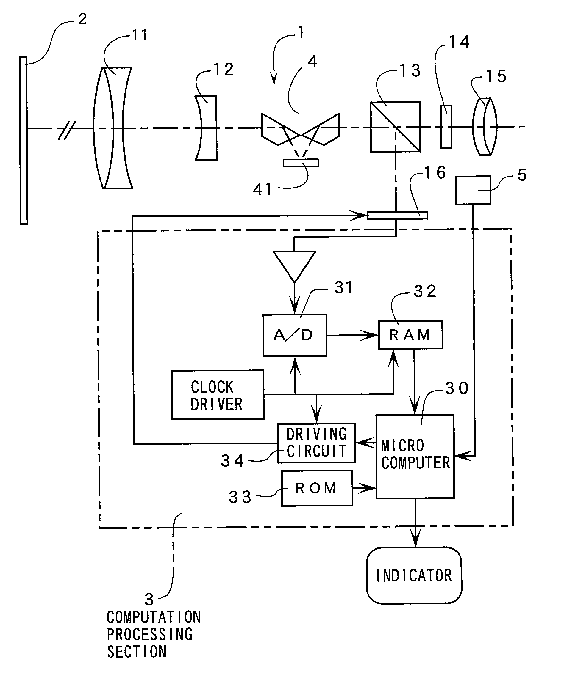
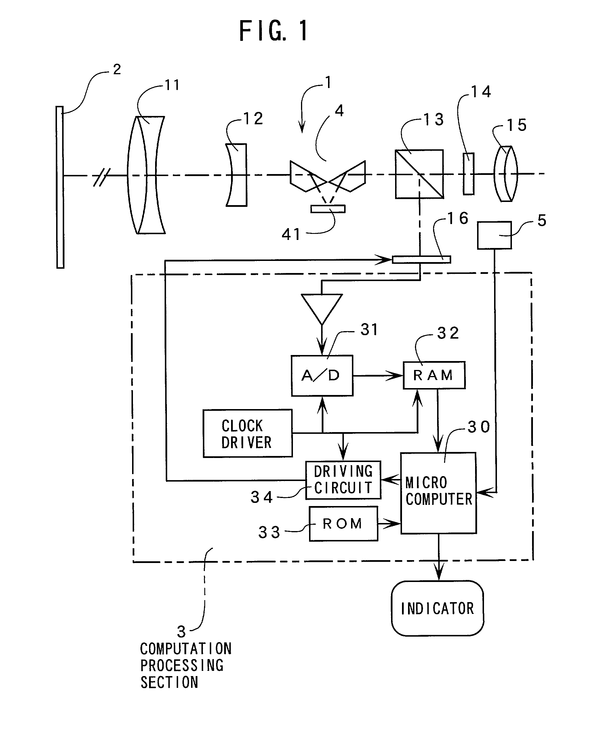
[0021] With reference to FIG. 1, reference numeral 1 denotes an optical system of a telescope. The optical system is to collimate the horizontal position of a levelling rod 2 which is vertically disposed in a measuring point which is located in front of the telescope. The image sensor of the telescope converts the image of the levelling rod 2 into an image signal in the form of an electronic signal, and outputs it to a computation processing section 3. The electronic level according to the present invention is constituted by the telescope and the computation processing section 3. Inside the telescope, there are disposed from the front end backward the following in the order mentioned, i.e., an objective lens 11, a focusing lens 12, a beam splitter 13, a focusing plate 14, and an eyepiece 15. Between the focusing lens 12 and the beam splitter 13, there is disposed a compensator 4. It is thus so arranged that, even if the telescope is inclined to some degree in the up and down directi...


PUM


Abstract

A vibration sensor is provided in a telescope. When vibrations are detected by the vibration sensor, the vibrating state of a reflecting mirror is estimated by the vibration state. When an image signal is captured by an image sensor, the frequency or period of capturing the image signal is varied depending on the state of vibrations of the reflecting mirror. In this manner, the time required for measurement is shortened, or the measuring error due to the swinging of the reflecting mirror is minimized.

Description

[0001] 1. Field of the Invention[0002] The present invention relates to an electronic level in which a light compensated by a compensator provided inside a telescope is received by an image sensor and a horizontal sighting position code is obtained by computation.[0003] 2. Description of the Related Art[0004] As this kind of electronic level, there has been known the following in Japanese Published Unexamined Patent Application No. 4959 / 1995. Namely, the light which is incident from an objective lens is passed through a compensator. The light is thereafter introduced into an image sensor and is converted into an image signal. The image signal is then captured by (or taken in) a computation section to thereby compute the height of the horizontal sighting position code.[0005] As is well known, the compensator is provided with reflecting mirrors which are swingably hung by a hanging wire. The light which is incident from the objective lens is once reflected by the reflecting mirrors. I...

Claims


Application Information

Patent Timeline
IPC IPC(8): G01C5/02G01C15/00G01C5/00G01H9/00
CPCG01H9/00G01C15/00
Inventor CHIBA, MINORU
Owner SOKKOIA COMPANY LIMITED
Why Eureka
Try Eureka