Intervertebral cage and method of use

a technology of vertebral cages and cages, which is applied in the field of human spinal implant devices, can solve the problems of complex surgical procedures for installing such devices, traumatic for patients, and inability to eliminate the need for anterior spinal column weight-bearing support,

Inactive Publication Date: 2002-05-09
DEPUY ACROMED INC
View PDF0 Cites 134 Cited by
  • Summary
  • Abstract
  • Description
  • Claims
  • Application Information

AI Technical Summary

Benefits of technology

[0009] The method of the invention facilitates inter-body fusion in the vertebral column by providing an improved prosthesis and method of installation. A space is first prepared for receiving a prosthetic device between two vertebrae. The banana-shaped spinal cage body is then surgically inserted into the space between the vertebrae. The banana-shaped cage body has an exterior surface and an interior surface, the interior surface defining an internal recess for receiving cancellous bone material during an implantation procedure. Preferably, the cage body is a ring of metal having evenly spaced openings about a circumference of the body. The cage body forms an interlinked mesh. The preferred cage body is formed of a hard metal alloy. Preferably, the cage body is formed of a titanium alloy.

Problems solved by technology

Genetic or developmental irregularities, trauma, chronic stress, tumors, and degenerative wear are typical causes which can result in spinal pathologies for which surgical intervention is necessary.
Recently, pedicel screws and rods have allowed surgeons to reduce degenerative conditions and immobilize the motion segment, but have not eliminated the need for weight-bearing support for the anterior spinal column.
The surgical procedures for installing such devices can be complicated and traumatic to the patient.

Method used


Image

  • Intervertebral cage and method of use
  • Intervertebral cage and method of use
  • Intervertebral cage and method of use

Examples


Embodiment Construction

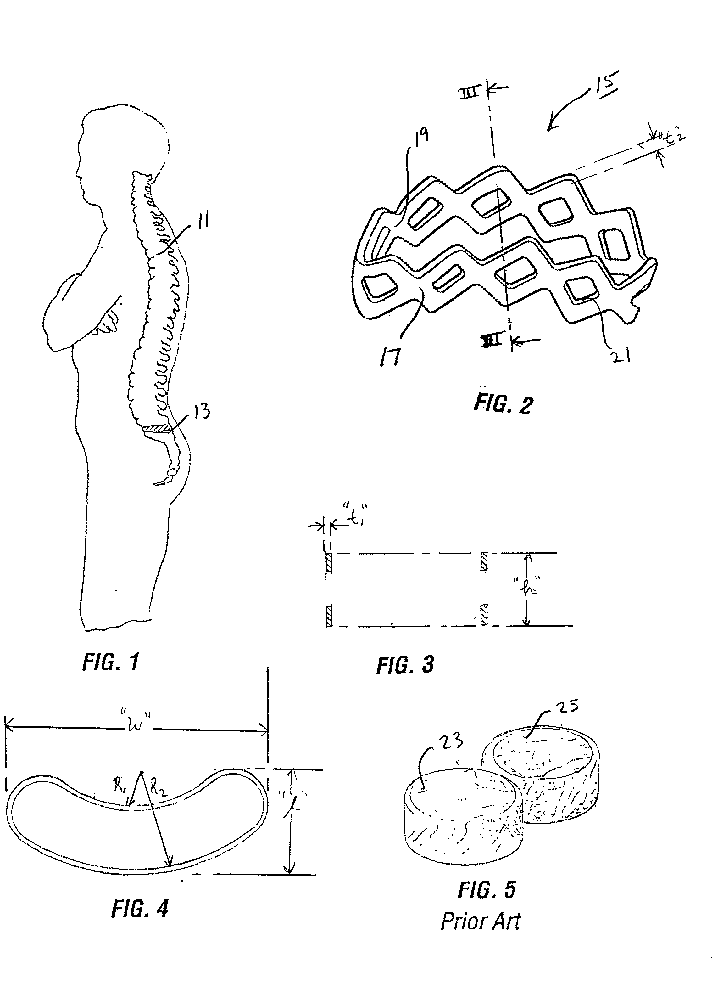
[0031] The bones and connective tissue of an adult human spinal column consists of more than 20 discrete bones coupled sequentially to one another by a tri-joint complex which consists of an anterior disc and the two posterior facet joints, the anterior discs of adjacent bones being cushioned by cartilage spacers referred to as intervertebral discs.

[0032] These more than 20 bones are anatomically referred to as being members of one of four classifications: cervical, thoracic, lumbar, or sacral. The cervical portion of the spine, which comprises the top of the spine, up to the base of the skull, includes the first 7 vertebrae. The intermediate 12 bones are the thoracic vertebrae and connect to the lower spine comprising the 5 lumbar vertebrae. The base of the spine is the sacral bones. The component bones of the cervical spine are generally smaller than those of the thoracic spine, which are in turn smaller than those of the lumbar region. The sacral region connects laterally to the ...


PUM

PropertyMeasurementUnit
widthsaaaaaaaaaa
widthsaaaaaaaaaa
widthsaaaaaaaaaa

Abstract

An intervertebral prosthesis for implantation between adjacent vertebrae of the human spine is shown. The prosthesis is formed as a unitary cage body configured and sized to be inserted between adjacent vertebrae in a single step implantation procedure. The cage body is banana shaped as viewed from above, the body having an exterior surface and an interior surface, the interior surface defining an internal recess for receiving cancellous bone material during an implantation procedure. The cage body can be formed as an interlinked mesh.

Description

[0001] 1. Field of the Invention[0002] The present invention relates generally to a human spinal implant device for implantation into intervertebral space between adjacent vertebral bones and to a surgical method for installing such a spinal implant assembly.[0003] 2. Description of the Prior Art[0004] Genetic or developmental irregularities, trauma, chronic stress, tumors, and degenerative wear are typical causes which can result in spinal pathologies for which surgical intervention is necessary. Various devices and techniques are disclosed in the prior art for immobilizing and / or fusing adjacent bones by implanting artificial devices in or on the spinal column. The region of the back which needs to be immobilized, as well as the individual variations in anatomy, determine the appropriate surgical protocol and implantation device which is best suited for the case at hand. Where a failure of the intervertebral disc is concerned, the inter-body fusion implant is often chosen.[0005] A...

Claims


Application Information

Patent Timeline
Patent Type & Authority Applications(United States)
IPC IPC(8): A61L27/00A61B17/70A61F2/00A61F2/28A61F2/30A61F2/44
CPCA61B17/701Y10S623/902A61F2/30965A61F2/442A61F2/4465A61F2002/2835A61F2002/30133A61F2002/30308A61F2002/30616A61F2002/30787A61F2002/4475A61F2230/0015A61F2230/0063A61F2310/00017A61F2310/00023A61B17/7032A61F2002/30593
Inventor SAZY, JOHN A.
Owner DEPUY ACROMED INC
Why Eureka
Try Eureka