User configurable multivariate time series reduction tool control method

Inactive Publication Date: 2002-05-23
GLOBALFOUNDRIES INC
View PDF1 Cites 43 Cited by
  • Summary
  • Abstract
  • Description
  • Claims
  • Application Information

AI Technical Summary

Problems solved by technology

One difficulty with multivariate methods is that, once an out-of-control situation is detected, determining which process variables caused the problem is difficult, based on a single or few indicator variables.
However, the conventional syste

Method used


Image

  • User configurable multivariate time series reduction tool control method
  • User configurable multivariate time series reduction tool control method
  • User configurable multivariate time series reduction tool control method

Examples


Embodiment Construction

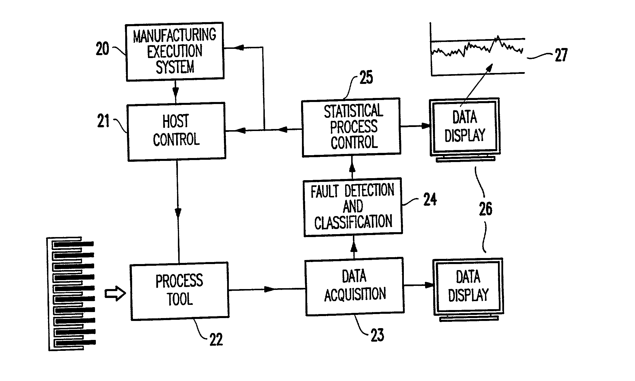
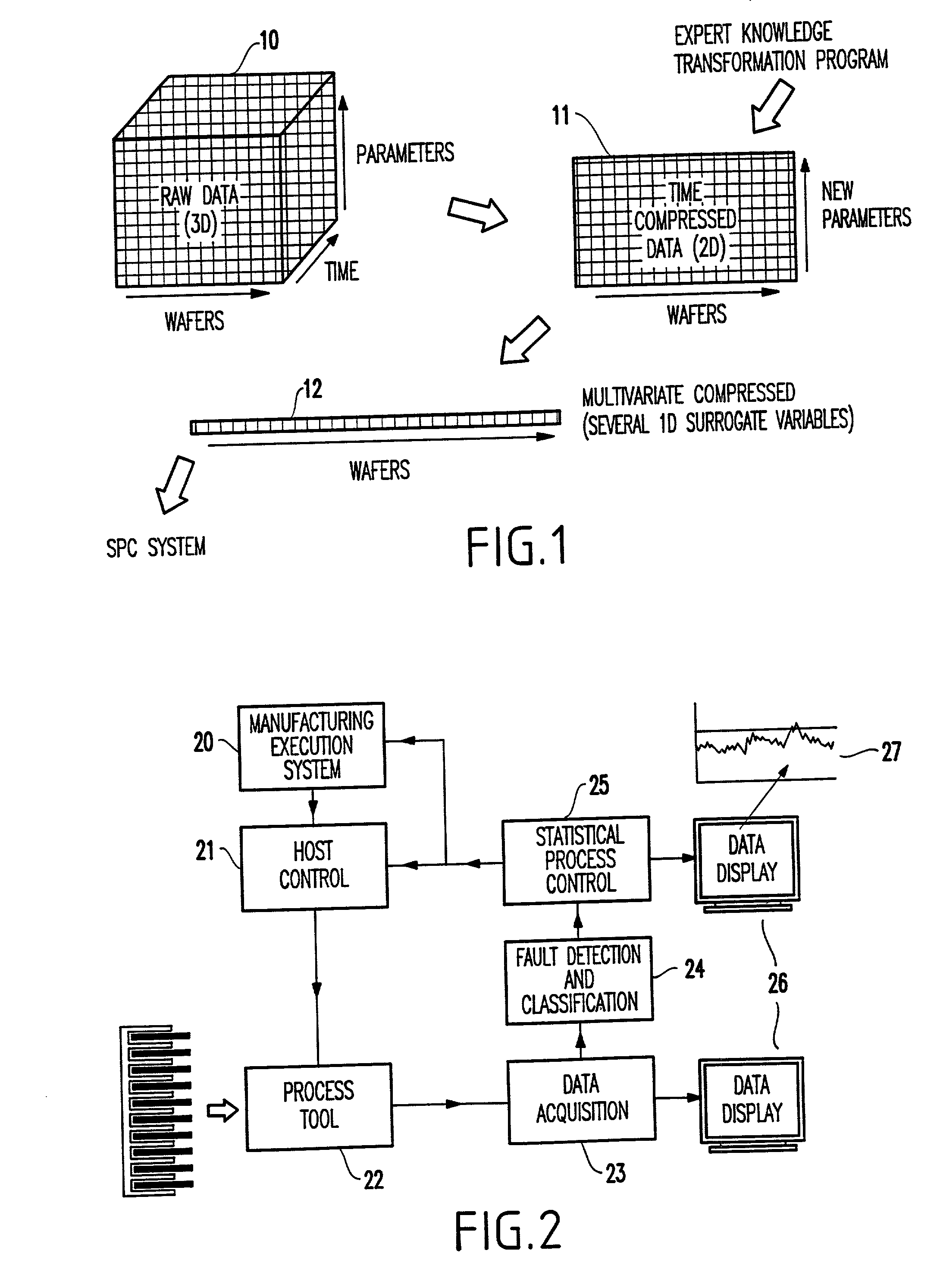
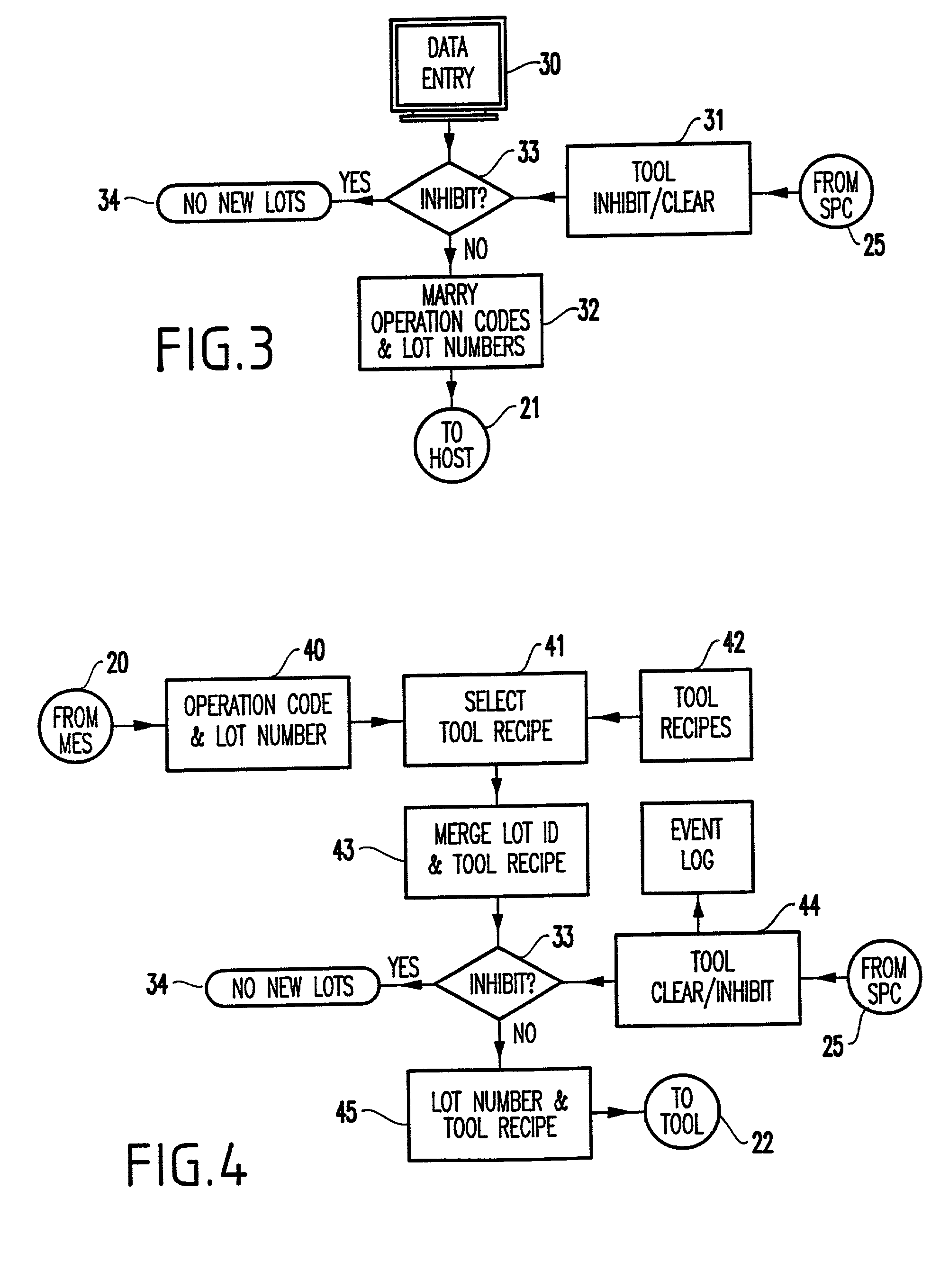
[0041] The inventive system determines if a parameter shift will put products at risk based on historical reference data and codified human expertise. When a significant change occurs, the system identifies the tool, the most likely out-of-control parameters, and suggests corrective action. The invention inhibits use of the tool until corrective action is taken. The invention also monitors process recipes for changes, authorized or unauthorized.

[0042] Further, the present invention provides a practical method for multivariate tool fault detection that prevents wafer mis-processing. As mentioned above, conventional methods and systems are not adequately able to distinguish between variations that do not affect products and variations that do affect products. The invention uses human expertise to distinguish which variations can be tolerated and which are of interest.

[0043] For example, some parameters change over long periods and are reset after a maintenance activity such as chamber...


PUM


Abstract

A method and structure for controlling a manufacturing tool includes measuring different manufacturing parameters of the tool, transforming a plurality of time series of the manufacturing parameters into intermediate variables based on restrictions and historical reference statistics, generating a surrogate variable based on the intermediate variables, if the surrogate variable exceeds a predetermined limit, identifying a first intermediate variable, of the intermediate variables, that caused the surrogate variable to exceed the predetermined limit and identifying a first manufacturing parameter associated with the first intermediate variable, and inhibiting further operation of the tool until the first manufacturing parameter has been modified to bring the surrogate value within the predetermined limit.

Description

[0001] 1. Field of the Invention[0002] The present invention generally relates to tool control system and solves the problem of mis-processing wafer lots / wafers by monitoring specific physical parameters of the tool set in real time. These parameters include any measurable quantifications relating to the process or tool, such as gas flow, temperature, pressure, power, etc.[0003] 2. Description of Related Art[0004] A manufacturing line is generally controlled using three logistic functions: lots must be routed to the proper tool set; recipes for various process steps must be routed to an individual process tool; and wafer lots must be matched to tool and then to a recipe. Further, two control functions exist. The first control function is to track the logistics functions. The second is to control the process tool parameters (e.g., to decide when a tool malfunction or tool fault has occurred.)[0005] The tool process parameters form a multivariate data set. The monitoring of such datas...

Claims


Application Information

Patent Timeline
IPC IPC(8): G05B23/02H01L21/66
CPCG05B23/0221H01L22/20G05B2219/45031
Inventor BUNKOFSKE, RAYMOND J.COLT, JOHN Z. JR.MCGILL, JAMES J.PASCOE, NANCY T.SURENDRA, MAHESWARANTAUBENBLATT, MARC A.GHIAS, ASIF
Owner GLOBALFOUNDRIES INC
Why Eureka
Try Eureka