Memory device having a systematic arrangement of logical data locations and having plural data portals

a data portal and memory device technology, applied in the field of memory devices and methods of storing and accessing data, can solve problems such as cumbersome scheduling, addressing and routing schemes, and achieve the effect of minimal contention between users and great flexibility

Inactive Publication Date: 2002-05-23
LOT 20 ACQUISITION FOUND LLC +1
View PDF0 Cites 8 Cited by
  • Summary
  • Abstract
  • Description
  • Claims
  • Application Information

AI Technical Summary

Benefits of technology

[0021] It is a further object of the invention to provide a data storage arrangement and a data retrieval arrangement that permit very efficient access to stored data, with minimal access contention.
[0022] It is yet another object of the present invention to provide a data storage arrangement and a data retrieval arrangement that allow the stored data to be disseminated widely and efficiently.

Problems solved by technology

Rather, these systems require cumbersome scheduling, addressing and routing schemes, to permit users to find and access data in the system.

Method used


Image

  • Memory device having a systematic arrangement of logical data locations and having plural data portals
  • Memory device having a systematic arrangement of logical data locations and having plural data portals
  • Memory device having a systematic arrangement of logical data locations and having plural data portals

Examples


first embodiment

[0103] A. Shift Registers

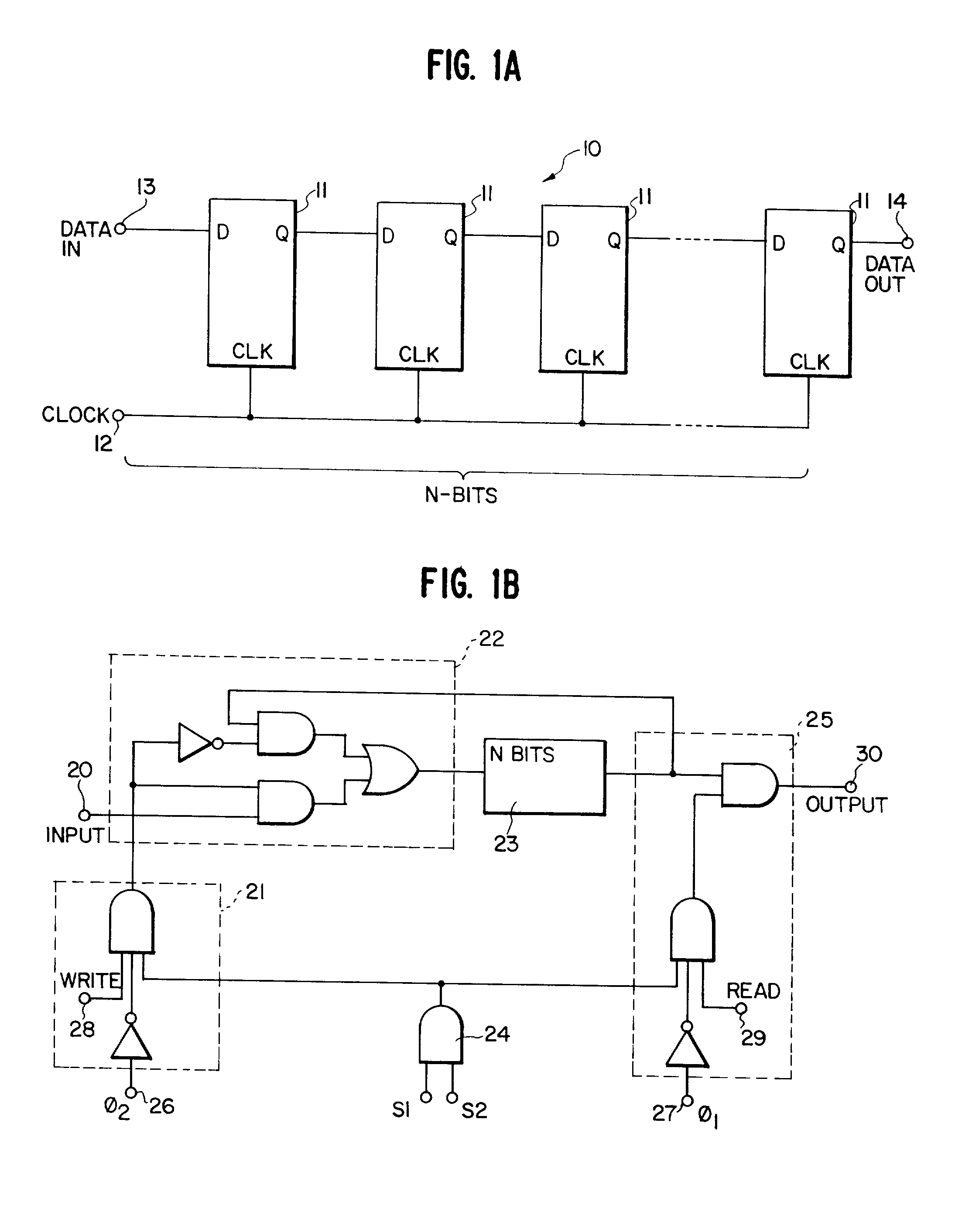
[0104] The preferred manner of embodying a memory device using shift registers is shown in FIG. 8A. FIG. 8A shows a long series of clocked shift registers 151 connected to form a ring 150. The ring 150 is constructed such that an entire title is capable of being stored on the ring. Typically, to store a two-hour movie, using MPEG2 as a data compression method, the ring should be able to store approximately 180 Gbits. The ring 150 is clocked by a clock source 152 which governs the rate of circulation of the data around the ring. The ring 150 is preferably clocked at such a rate to deliver (i.e., output) the title at a rate required by the receiver.

[0105] If the clock rate required cannot be attained by one shift register, many registers in parallel can be used to obtain the rate required. FIG. 8B illustrates one possible such embodiment in which two parallel rings are constructed, each comprising clocked shift registers 151 connected in series. FIG. 8C illus...

second embodiment

[0117] B. Charge Coupled Devices

[0118] A further, preferred alternative for embodying the memory device is to employ CCDs 171 (Charge-Coupled Devices) as the registers 151, as shown in FIG. 9, to form a ring memory device 170. If the ring 170 is constructed using CCDs 171, then each CCD 171 must be pumped by a clock source 172. Further, some form of regenerating means 176 must be coupled between each CCD 171. Possibilities for the regenerating means 176 include logic gates, as above. The individual CCDs simply function as registers in this embodiment, and the ring memory device 170, overall, functions similarly to the ring memory device 150 described with reference to FIG. 8.

third embodiment

[0119] C. Delay Lines

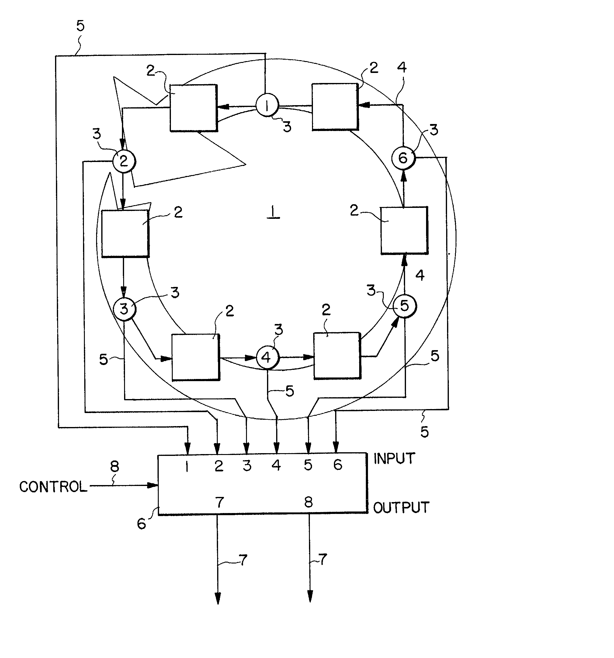
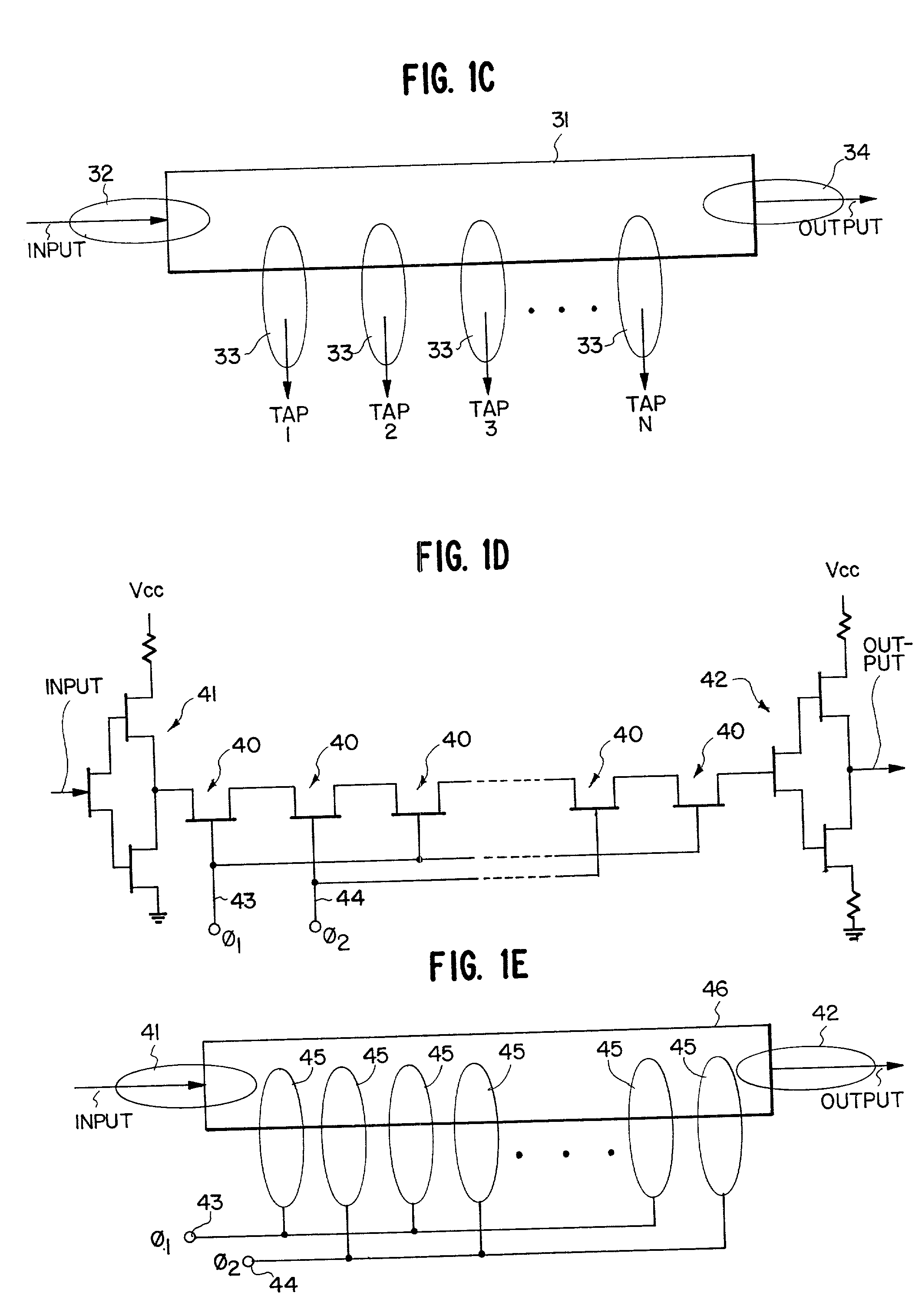
[0120] A further implementation of a ring memory device, using delay lines 181 as the storage devices, is shown in FIG. 10. Access gates 182 connect the individual delay lines 181 together. Preferably, the access gates 182 provide data ingress lines 183, data egress lines 184 and access control lines 185. The delay lines 181 themselves are preferably provided with egress ports 186 in addition to those provided at the access gates. In operation, signals transmitted over the access control lines 185 activate the ingress lines 183 or the egress lines 184, thereby allowing data to be input to or output from the ring memory device 180, respectively. If it is desired to output the title via one or more of the additional egress ports 186, appropriate gates at ends of the egress ports 186 are controlled accordingly. Otherwise, operation is analogous to that described with respect to FIG. 8.


PUM


Abstract

A method and an apparatus for storing data provide data memory in a systematic, cyclical arrangement, provide plural data portals in an arrangement defined by modular arithmetic, and provide sequential, relative movement between the data memory and the data portals. When one or more of the plural portals is selected, data can be input or output in a manner which is predictable, straight-forward, free of scheduling constraints, and very efficient, without contention between the separate portals. Also disclosed are a method and apparatus which provide data memory in a systematic, cyclical arrangement, provide a systematic arrangement of plural data outputs, and provide sequential, relative movement between the data memory and the data outputs. The memory devices of the present invention can be designed so that the memory device circulates data either through or past fixed portals. Alternatively, the data can be stored in fixed locations and the portals moved from location to location. Preferred embodiments of the invention utilize semiconductor memory technology in order to implement the memory devices. Another set of embodiments utilizes memory storage media capable of confining propagating waves in order to implement the memory devices.

Description

RELATED APPLICATION INFORMATION[0001] This application is a divisional of co-pending application Ser. No. 08 / 249,265, filed May 25, 1994, the disclosure of which is incorporated herein by reference. Application Ser. No. 08 / 249,265, in turn, is a continuation-in-part of application Ser. No. 08 / 136,185, filed Oct. 15, 1993, and issued as U.S. Pat. No. 5581,479 on December 3, 1996, the disclosure of which is also incorporated herein by reference.[0002] 1. Field of the Invention[0003] The present invention relates generally to memory devices and methods of storing and accessing data. More particularly, the invention concerns storage of data in a systematic arrangement of data locations in a manner that establishes a systematic relationship between the data locations and points used for accessing the data, to provide independent and extremely efficient access to, and dissemination of, the stored data streams.[0004] 2. Description of Relevant Background[0005] Consumer demand for enhanced ...

Claims


Application Information

Patent Timeline
Patent Type & Authority Applications(United States)
IPC IPC(8): G06F3/06G06F12/00G06F13/00G11C19/00G11C19/18H04N7/08H04N7/10H04N7/173H04N21/231
CPCG11C19/00G11C19/188H04N21/231H04N7/10H04N7/17336H04N7/08
Inventor MCLAUGHLIN, ROBERT B.PLUMHOFF, LAWRENCE C.BULLEN, JAMES M.
Owner LOT 20 ACQUISITION FOUND LLC
Why Eureka
Try Eureka