Mesh bearing damper for an energy storage rotor

Inactive Publication Date: 2002-05-30
BEACON POWER LLC
View PDF5 Cites 30 Cited by
  • Summary
  • Abstract
  • Description
  • Claims
  • Application Information

AI Technical Summary

Problems solved by technology

As a result, in each instance, fluid is likely to escape from the pressure chamber.
Were such fluid, especially oil, to escape into the evacuated chamber of an energy storage system, the effect on the system would be catastrophic.
Each of these patents, however, is likely to leak fluid.
Therefore, they are unsuitable for use in conjunction with an evacuated energy

Method used


Image

  • Mesh bearing damper for an energy storage rotor
  • Mesh bearing damper for an energy storage rotor
  • Mesh bearing damper for an energy storage rotor

Examples


Embodiment Construction

[0022] Flywheel-based energy storage devices comprise relatively simple devices for readily storing and recovering energy. Conceptually, as a flywheel spins, mechanical kinetic energy is stored, e.g., primarily in the outermost portion (the "rim") of the flywheel assembly. The amount of energy stored in a flywheel assembly is directly proportional to its mass and to the square of the rotational velocity of the flywheel. Consequently, those skilled in the art continue to develop flywheels that rotate at ever-increasing velocities.

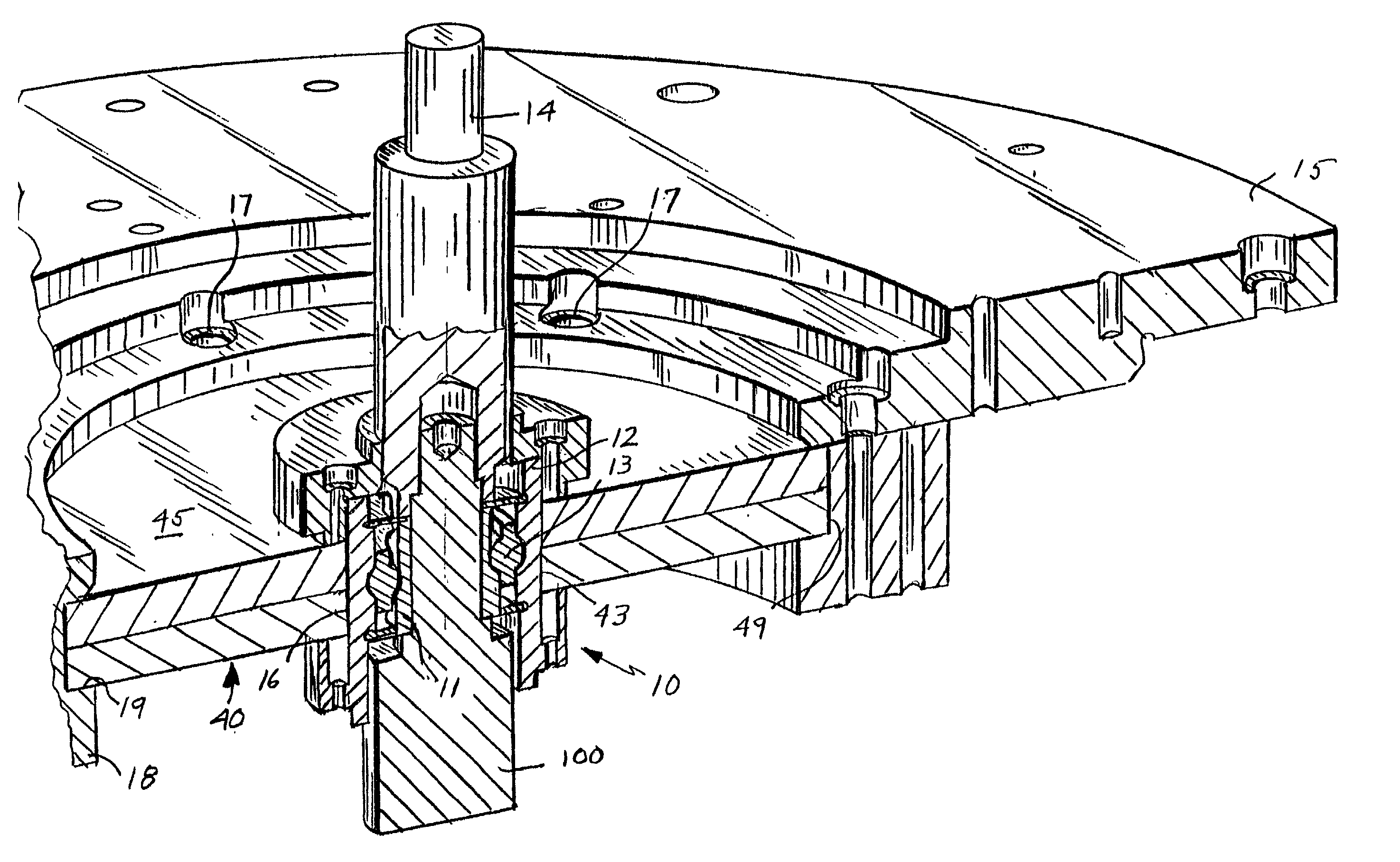
[0023] In accordance with FIG. 3, a rotating shaft 100 turns the flywheel of an energy storage device. A plurality of bearings 10 supports and guides the shaft 100; permits free motion between the moving rotary shaft 100 and fixed parts; minimizes energy loss and wear and tear due to friction; and dampens vibrations produced by the rotary shaft 100 and / or flywheel assembly. Notwithstanding the significance of the other, interrelated bearing 10 functions, sup...


PUM

PropertyMeasurementUnit
Linear densityaaaaaaaaaa

Abstract

The present invention discloses a fluid-free mesh bearing damper, e.g., for a flywheel energy storage device. The disclosed mesh bearing damper is uniquely suitable for use in combination with flywheel assemblies, which typically are evacuated by one or more pumps to create a vacuum to substantially minimize energy loss due to air friction, because, among others, the disclosed bearing damper does not use fluids, e.g., pressurized oil, that may affect deleteriously the operation of the pumps. Moreover, the disclosed bearing damper damps vibrations, i.e., reduces the amplitude of the vibrations, induced by the rotating shaft, deflection of the shaft, and/or by the misalignment, or eccentricity, of the shaft; substantially lowers the load on the bearings, which enhances the life of the bearings and facilitates magnetic levitation; and transfers heat away from the bearings, which, further, enhances the life of the bearings. The disclosed bearing damper comprises at least one, e.g., copper, aluminum, carbon fiber, etc., circular mesh disk, which is in tight interference fit with the shaft bearing at the disk's inner periphery.

Description

[0001] The present invention relates to a damping device for the bearings of an energy storage system. More precisely, the invention relates to a fluid-less, mesh bearing damper for bearings supporting rotors for a flywheel assembly, which substantially lowers the amplitude of vibrations; substantially lowers loads on the rotor; and enhances heat transfer away from the bearings, prolonging bearing life.DESCRIPTION OF THE RELATED ART[0002] Energy storage systems, which internally produce and store kinetic energy in high speed rotors, or flywheels, have been developed as an alternative to batteries and other means of storing energy for at least about 30 years. Energy storage systems typically comprise an energy-storing rotor, which includes an outer rim commonly made of high-strength, low-density composite fibers that maximize energy storage density, and a high-powered, high-strength generator, which turns the rotor at high rotational velocities. To reduce energy loss through air fric...

Claims


Application Information

Patent Timeline
IPC IPC(8): F16C27/04F16F1/362F16F15/315
CPCF16C27/04Y02E60/16F16F15/3153F16F1/362F16C2361/55
Inventor KABIR, OMAR M.
Owner BEACON POWER LLC
Why Eureka
Try Eureka