Machine tool with roof covering bellow

Inactive Publication Date: 2002-06-20
STAMA MASCHFAB GMBH
View PDF3 Cites 14 Cited by
  • Summary
  • Abstract
  • Description
  • Claims
  • Application Information

AI Technical Summary

Problems solved by technology

All these machine tools have the disadvantage that only devices and work pieces with certain dimensions can be loaded and discharged through the opening provided in the front wall, a crane loading of very bulky and/or very heavy work pieces and/or devices is only possible by using a U-shaped fork laterally engaging through the opening into the working area.
Such a loading is, however, disadvantageous both of static reasons and of handling reasons.
Such machine tools have the disadvantage, however, that the door is very heavy and very large, so that it is large-scale in design, and the guidings have to be configured correspondingly.
This results not only in very expensive and awkward designs, the whole construction height of the machine tool is, moreover, very large, as the door has to extend up to over the height of the headstock.
A further disadvantage in suc

Method used


Image

  • Machine tool with roof covering bellow
  • Machine tool with roof covering bellow
  • Machine tool with roof covering bellow

Examples


Embodiment Construction

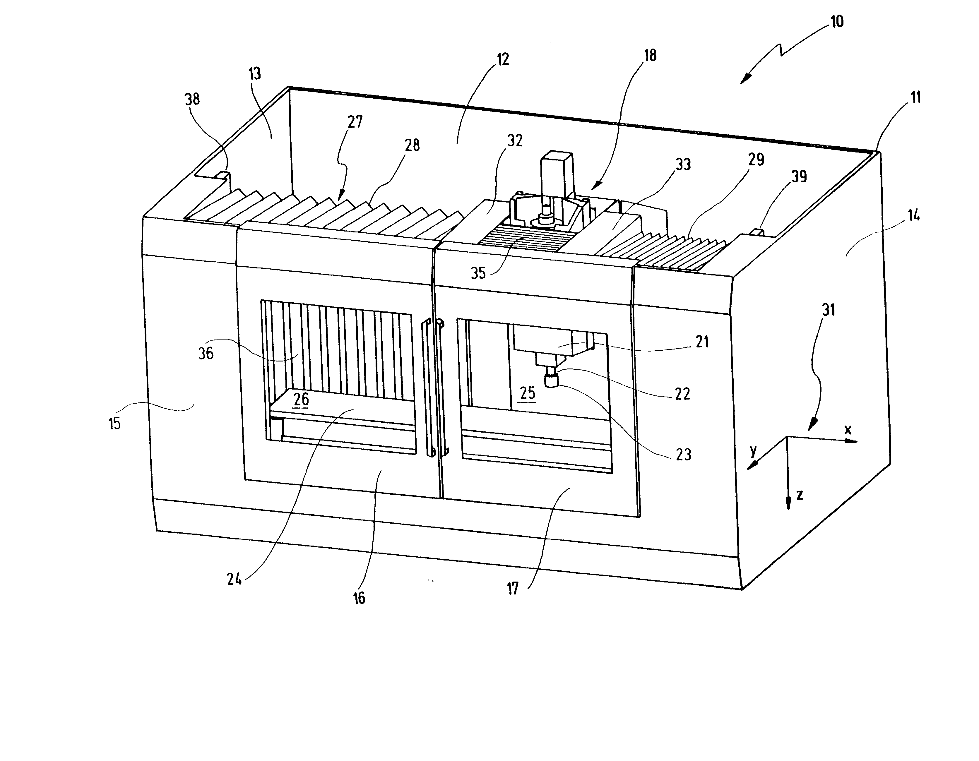
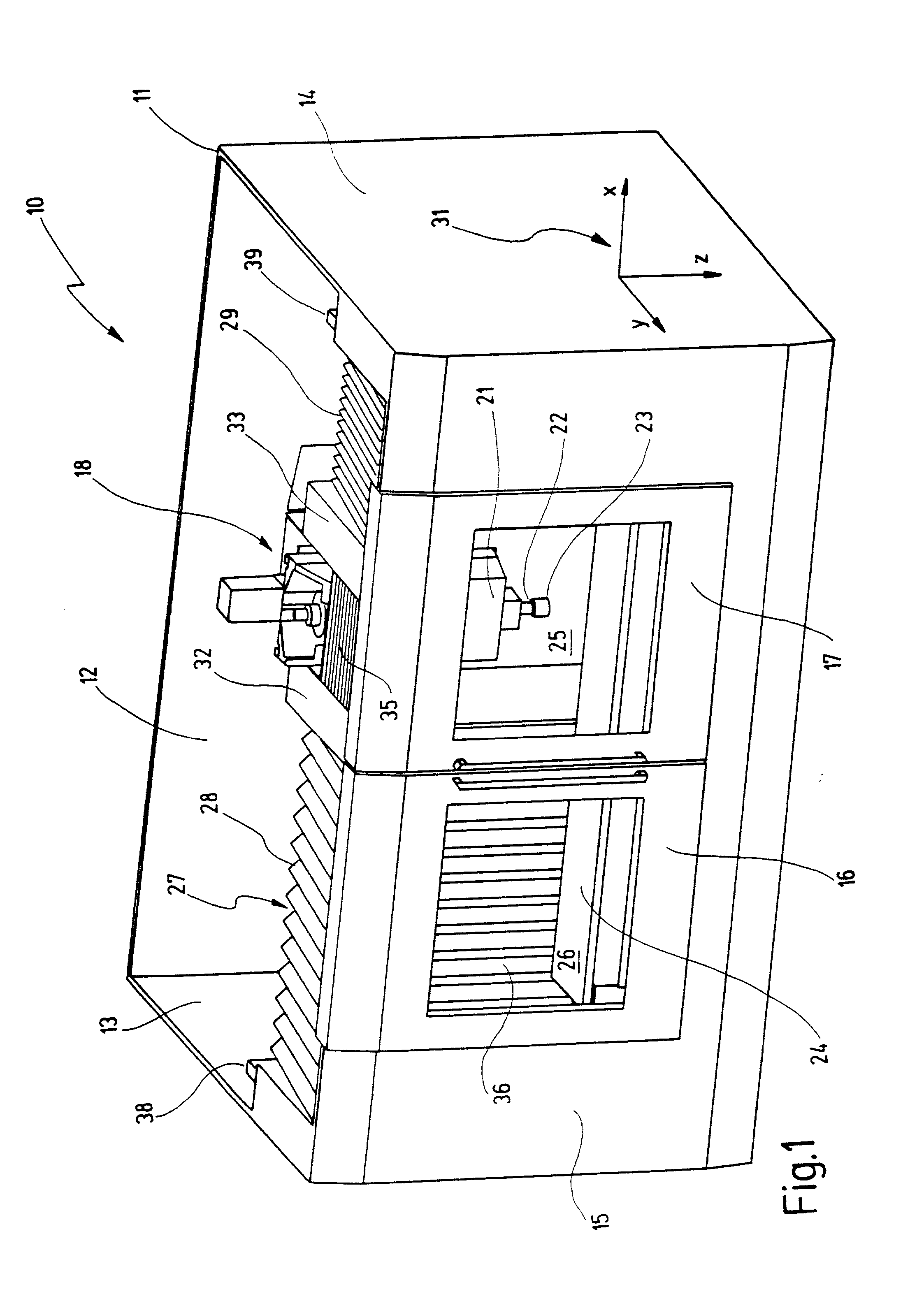
[0046] In FIG. 1, a machine tool is designated with 10 and comprises a housing 11 that has a rear wall 12, two side walls 13, 14 and a front wall 15. At front wall 15, two sliding doors 16, 17 are provided, which can be slid to the left or to the right.

[0047] In housing 11, a headstock 18 is provided, on which a spindle head 21 with a main spindle 22 is mounted, in which a tool 23 is clamped. Beneath tool 23, a work piece table 24 can be seen, onto which work pieces to be machined can be laid.

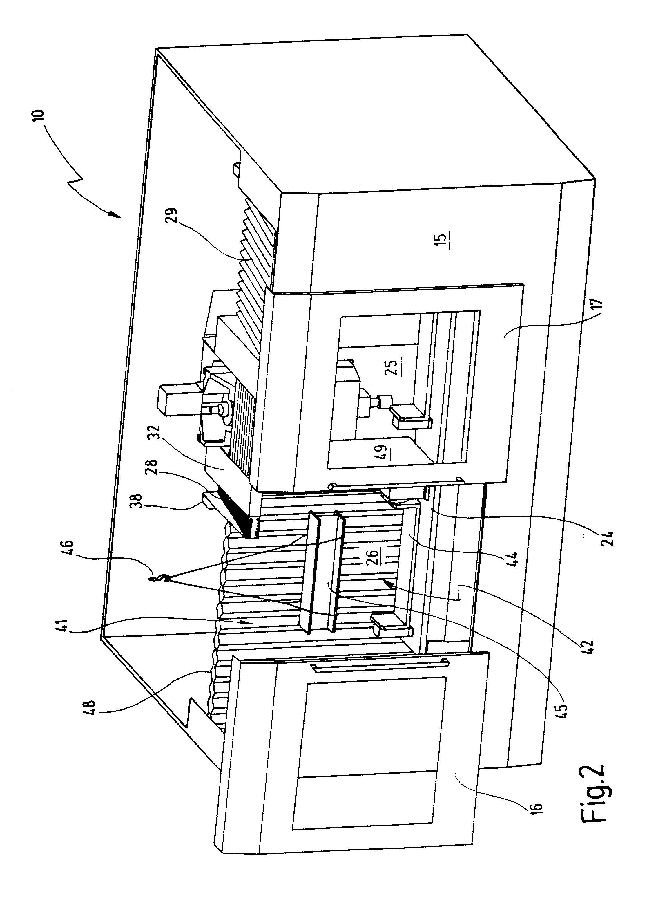
[0048] Machine tool 10 has a working area which is divided into a right section 25 and into a left section 26. Working area 25, 26 is laterally covered by side walls 13 and 14, to the front by front wall 15 and to the top by a roof covering 27, which has a left upper bellow 28 and a right upper bellow 29.

[0049] At the right in FIG. 1, a system of coordinates 31 is shown, which describes relative to work piece table 24 the movement directions of tool 23 with x, y and z. These movements are effec...


PUM

PropertyMeasurementUnit
Fractionaaaaaaaaaa
Magnetismaaaaaaaaaa

Abstract

A machine tool comprises a working area, closed by walls and a roof covering, in which a device for receiving a work piece is arranged, and a headstock with a main spindle is arranged, into which tools for machining the work piece can be clamped. Device and headstock are movable relatively to each other. In a front wall an opening lockable by a door leads into the working area. At least one part of the roof covering is movable between two positions in such a way that it locks the working area to the top in a first position and releases same to the top for loading in a second position.

Description

[0001] This application is a continuation application of International Patent Application PCT / EP00 / 08481.[0002] 1. Field of the Invention[0003] The present invention relates to a machine tool with a working area closed by walls and a roof covering, in which working area a device for receiving a work piece and a headstock with a main spindle are arranged, into which main spindle tools for machining the work piece can be clamped, whereby the device and the headstock are movable relatively to each other, and whereby in a front wall an opening to be closed by a door leads into the working area.[0004] 2. Related Prior Art[0005] Such machine tools are known from the prior art.[0006] In known machine tools, a housing is provided, which completely surrounds the working area and the headstock, the housing being further divided by inner walls, so that the working area is closed towards the guide rails and other equipments of the machine tool. This closed working area ensures that chips arisin...

Claims


Application Information

Patent Timeline
IPC IPC(8): B23Q11/08
CPCY10T409/30392B23Q11/0816
Inventor GRUND, PETERSCHMID, SIEGFRIEDBLAZEK, PAVELNIEDERBERGER, WALTER
Owner STAMA MASCHFAB GMBH
Why Eureka
Try Eureka