Replenishable stent and delivery system

a stent and stent technology, applied in the field of stents, can solve the problems of affecting the otherwise unaffected area, the delivery system must be easily disengaged from the stent, and further damage to the afflicted area,

Inactive Publication Date: 2002-06-20
BOSTON SCI CORP
View PDF27 Cites 130 Cited by
  • Summary
  • Abstract
  • Description
  • Claims
  • Application Information

AI Technical Summary

Benefits of technology

[0046] It is a further object of this invention to provide a method and apparatus for delivering a stent and therapeutic agent to a vessel which is relatively simple and inexpensive to produce and use.

Problems solved by technology

Second, the delivery system must facilitate the deployment of the stent once located in a vessel.
Third, the stent delivery system must easily disengage from the stent after the stent is deployed.
However, it is still a fact that each insertion and extraction risks further damage to afflicted areas and damage to otherwise unaffected areas through which the instruments pass and can add to patient trauma.
Moreover, insertion and withdrawal of additional instruments in sequence increases the time of the physician, staff, and medical facility, and the cost of multiple instruments.
However, none of these references disclose a stent that enable both the release of a therapeutic agent therefrom and the charging or recharging of the stent with a therapeutic agent once positioned within the body to permit delivery of therapeutic agent to replenish a stent.
None provides a structure for improving the efficiency of percutaneous transluminal procedures and other internal procedures by providing a stent for dispensing a therapeutic agent that can receive additional therapeutic agents in vivo and a therapeutic agent delivery system for replenishing the therapeutic agent dispensed from the stent.
None disclose a delivery system and method capable of replenishing a therapeutic agent after it has been depleted from an original supply.

Method used


Image

  • Replenishable stent and delivery system
  • Replenishable stent and delivery system
  • Replenishable stent and delivery system

Examples


Embodiment Construction

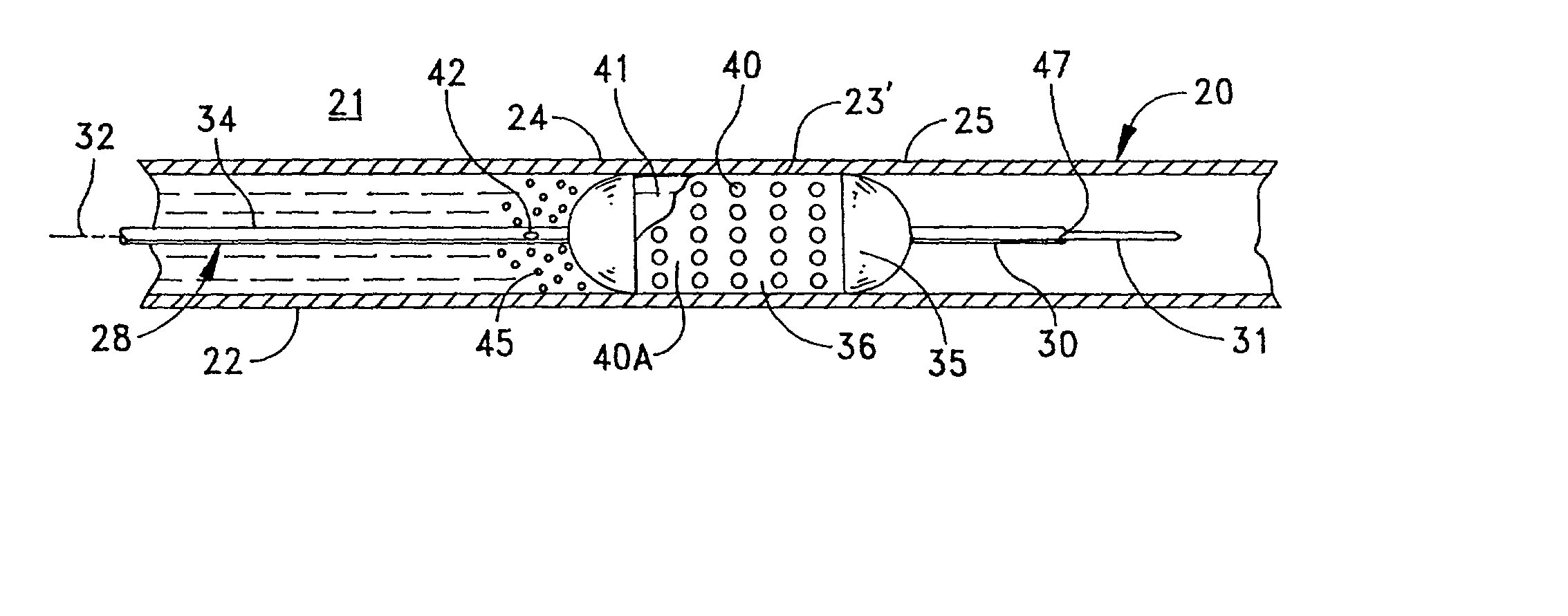
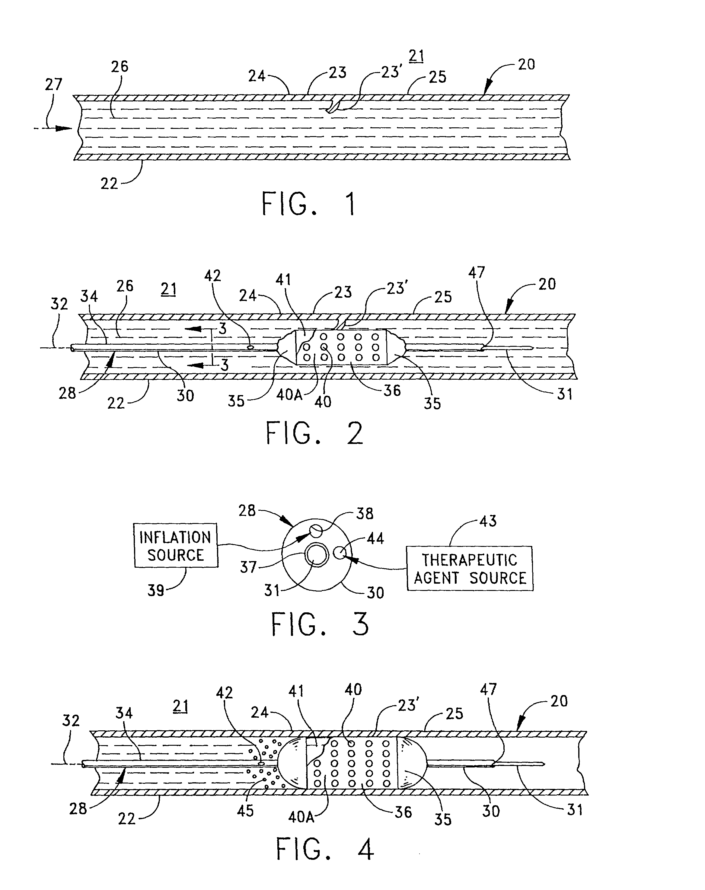
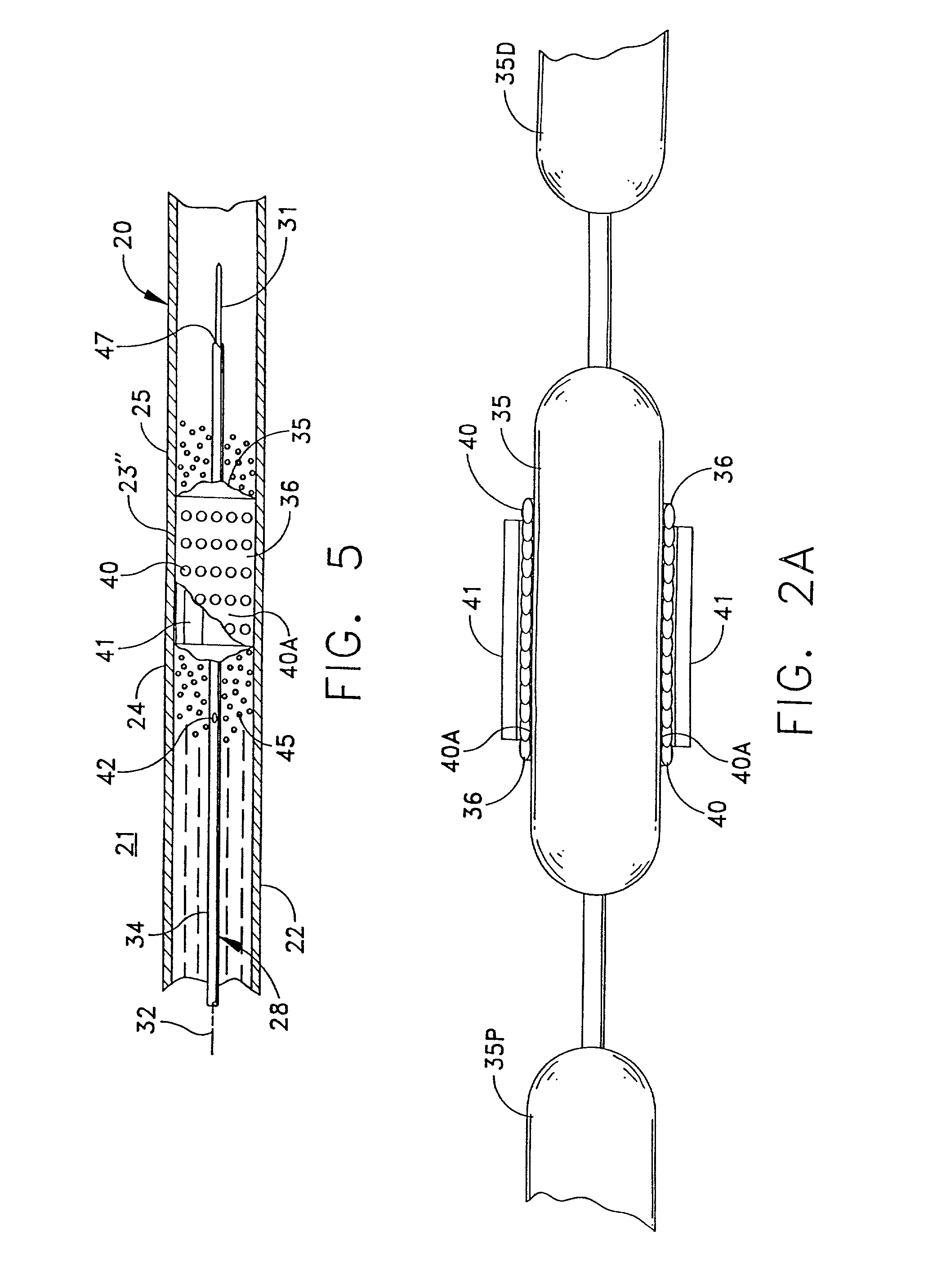
[0067] FIG. 1 depicts, in simplified form, a single-passage, tubular vessel 20 through tissue 21, such as peri-arterial tissue, defined by a vessel wall 22. Although FIG. 1, and the other similar figures, depict a vessel wall as comprising a single homogeneous layer, it will be recognized that an actual vessel wall has multiple layers. However, this invention can be understood by referring to the simplified, homogenous representation in the figures. Furthermore it should be appreciated that the vessel 20 is intended to be representative generally of any of the diverse passageways found in a patient's body.

[0068] FIG. 1 illustrates an irregularity or abnormality in the wall of the vessel 20 at an afflicted or irregular wall portion 23 in the vessel wall 22 that is disposed between essentially normal wall portions 24 and 25. In this case, the irregular wall portion 23 includes a flap 23' that can develop due to the weakening and / or stretching of the walls in otherwise normal wall 22. ...


PUM


Abstract

Apparatus and a method for treating an irregularity in a wall of a vessel of a patient defined by an irregular or afflicted wall portion with adjacent normal wall portions comprises a catheter having a distal end portion for being guided through the vessel to the site of the irregularity. A balloon associated with said distal end portion of the catheter for selective inflating to contact the walls of the vessel urges a stent carried by the distal end portion of the catheter in a constricted condition for passage through the vessel into an expanded form with the stent spanning the afflicted wall portion and contacting the adjacent wall portions. The catheter is formed with lumens for inflating the balloon, for receiving a guidewire for guiding the catheter through the vessel, and for connecting a port in the catheter proximate the afflicted wall portion to enable delivery of a therapeutic agent into the vessel to contact the stent and the irregular wall portion.

Description

[0001] This is a continuation in part of copending application Ser. No. 0 / 507,244 filed Jul. 27, 1995 for a Stent and Therapeutic Delivery System which is a continuation of Ser. No. 08 / 268,999 filed Jun. 30, 1994 for a Stent and Therapeutic Delivery System (now U.S. Pat. No. 5,439,446 granted Aug. 8, 1995) which applications are all assigned to the same assignee as the present invention.[0002] 1. Field of the Invention[0003] The present invention generally relates to stents positionable within the body of a patient and more particularly relates to a stent for delivering a therapeutic agent therefrom and a method and system for delivery of a therapeutic agent to replenish the stent.[0004] 2. Description of Related Art[0005] Physicians often use medical guidewires and catheters in combination. Medical guidewires are devices navigable through narrow passages in the body such as vessels, tubes, ducts, passages and the like, hereinafter collectively referred to as vessels. A physician co...

Claims


Application Information

Patent Timeline
Patent Type & Authority Applications(United States)
IPC IPC(8): A61F2/00A61F2/82A61M25/00A61M29/02
CPCA61F2/82A61F2/958A61F2250/0067A61M2025/1093A61M2025/0057A61M2025/1013A61M2025/105A61M25/104
Inventor BARRY, JAMES
Owner BOSTON SCI CORP
Why Eureka
Try Eureka