
Apparatus and method for measurement of fluid viscosity

a fluid viscosity and apparatus technology, applied in the field of apparatus and method for measuring fluid viscosity, can solve the problems of two wave trains affecting the outer side of the blade, no reliable method available to date,

Inactive Publication Date: 2002-06-27
UNIV OF NORTHERN IOWA RES FOUND
View PDF0 Cites 15 Cited by
  • Summary
  • Abstract
  • Description
  • Claims
  • Application Information

AI Technical Summary

Problems solved by technology

While Stokes (1819-1903), father of modern fluid dynamics, recognized that the attenuation of surface waves could be exploited to measure viscosity without the use of a foreign object, no reliable method has been available to date.
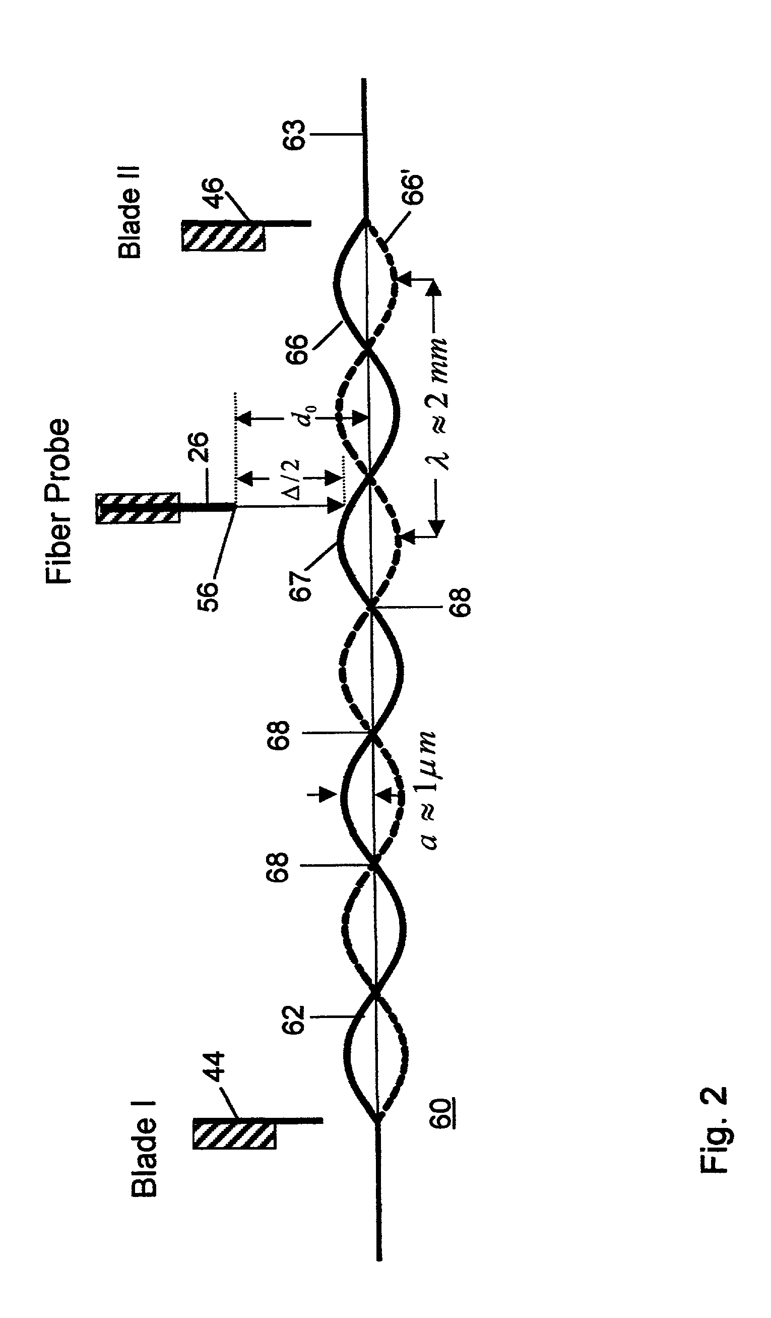
If the distance between the two blades is chosen to be a half odd-integer wavelength, the two wave trains interfere destructively on the outer sides of the blades.

Method used


Image

  • Apparatus and method for measurement of fluid viscosity
  • Apparatus and method for measurement of fluid viscosity
  • Apparatus and method for measurement of fluid viscosity

Examples


Embodiment Construction

[0062] The invention system has been employed to determine the kinematic viscosity of pure water over temperature to demonstrate the utility and accuracy of the system by comparing data published in the CRC Handbook of Chemistry and Physics (CRC, Cleveland, Ohio, 1999) with the empirical data provided by this invention apparatus and method. FIG. 8 gives our measured values of the kinematic viscosity, .eta. / .rho., vs. the temperature for pure water. The solid line in the figure is a second order polynomial fit to the published data for pure water and is included for comparison. Since water has a very small viscosity to begin with, measuring the temperature variation of its viscosity constitutes a severe test of our method. The excellent results presented in FIG. 8 show that the non-contact method described provides a sensitive new alternative to flow viscometry. Furthermore, the non-contact nature of the method provides another clear advantage by eliminating the possibility of contam...


PUM

PropertyMeasurementUnit
frequencyaaaaaaaaaa
wavelengthaaaaaaaaaa
voltageaaaaaaaaaa

Abstract

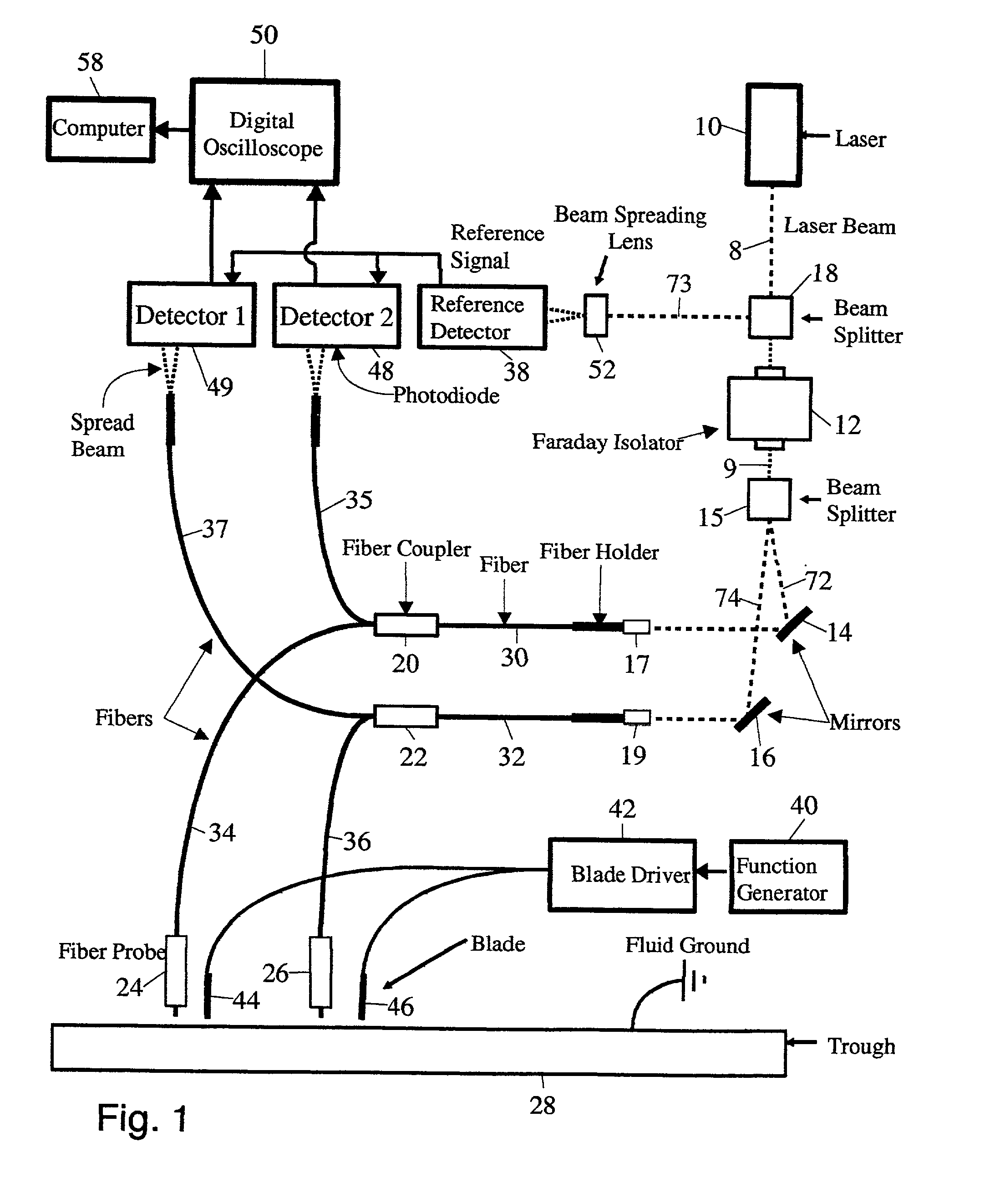
A non-contact apparatus and method for mapping the wave profile of capillary waves on a fluid surface to determine viscosity of the fluid. Two conducting blades coupled to a sine wave generator are positioned spaced laterally above and near the surface of the fluid to generate a standing capillary wave on the fluid surface between the blades. A laterally moveable fiber optic probe is coupled to a laser to transmit laser light toward the fluid surface and to receive reflected light from the fluid surface. Part of the laser light reflects from the end of the probe and creates an interference pattern with the light reflected from the fluid surface. The light reflected from the end of the probe and from the fluid surface are combined to form an interference signal which is analyzed to obtain the amplitude of the wave directly under the probe. By moving the probe laterally, nodes on the standing wave may be detected to find the wavelength of the capillary wave. One blade may be decoupled from the sine wave generator and the fiber optic probe moved laterally to determine the wave amplitude of a traveling wave as a function of distance which is then used to determine viscosity.

Description

[0001] Not Applicable.[0002] Not Applicable.[0003] The present invention pertains to non-contact measurement of fluid viscosity by use of a miniature laser interferometer. BACKGROUND OF THE INVENTION The invention is a new process for measuring the viscosity of fluids without making any physical contact with the fluid. Viscosity is a manifestation of fluid friction. The standard method for measuring viscosity was invented by the French physician Jean Louis Poiseuille (1799-1869) who devised the first flow viscometer. In the past two centuries many other eminent scientists, including James Clerk Maxwell, have tried their hands at inventing alternative viscometers. In principle all the current methods (Couette, falling-sphere, oscillating disk, and cone-and-plate viscometers) exploit the resistance experienced by an object in contact with and in relative motion to the fluid. While Stokes (1819-1903), father of modern fluid dynamics, recognized that the attenuation of surface waves cou...

Claims


Application Information

Patent Timeline
Patent Type & Authority Applications(United States)
IPC IPC(8): G01N11/00
CPCG01N11/00
Inventor BEHROOZI, FEREDOON
Owner UNIV OF NORTHERN IOWA RES FOUND
Learn More