
Method for measuring thermal diffusivity and interface thermal resistance

a technology of thermal diffusivity and interface, which is applied in the direction of heat measurement, material heat development, instruments, etc., can solve the problems of insufficient progress in the measurement of thermophysical properties of such a thin film structure, prior art method as described in the above has been proved to be extremely difficult in separately measuring the thermal diffusivity of each film, and the above-mentioned measuring method has been found to be extremely difficult in measuring the thermal diffusivity of a non-metal thin film

Inactive Publication Date: 2002-06-27
NAT INST OF ADVANCED IND SCI & TECH
View PDF0 Cites 17 Cited by
  • Summary
  • Abstract
  • Description
  • Claims
  • Application Information

AI Technical Summary

Problems solved by technology

On the other hand, although there has been a great progress in the measurement of electric, magnetic and optical properties of the above described thin film, the present situation is that there has not been a sufficient progress in the measurement of thermophysical properties of such a thin film structure.
However, in the case where it is required to measure an interface thermal resistance as well as a thermal diffusivity of a multi-layered film structure, the prior art method as described in the above has been proved to be extremely difficult in separately measuring a thermal diffusivity of each film layer and interface thermal resistance.
For this reason, the aforementioned measuring method has been found to be extremely difficult in measuring the thermal diffusivity of a non-metal thin film such as a semiconductor thin film.

Method used


Image

  • Method for measuring thermal diffusivity and interface thermal resistance
  • Method for measuring thermal diffusivity and interface thermal resistance
  • Method for measuring thermal diffusivity and interface thermal resistance

Examples


Embodiment Construction

[0023] An embodiment of the present invention will be described below in accordance with the accompanying drawings.

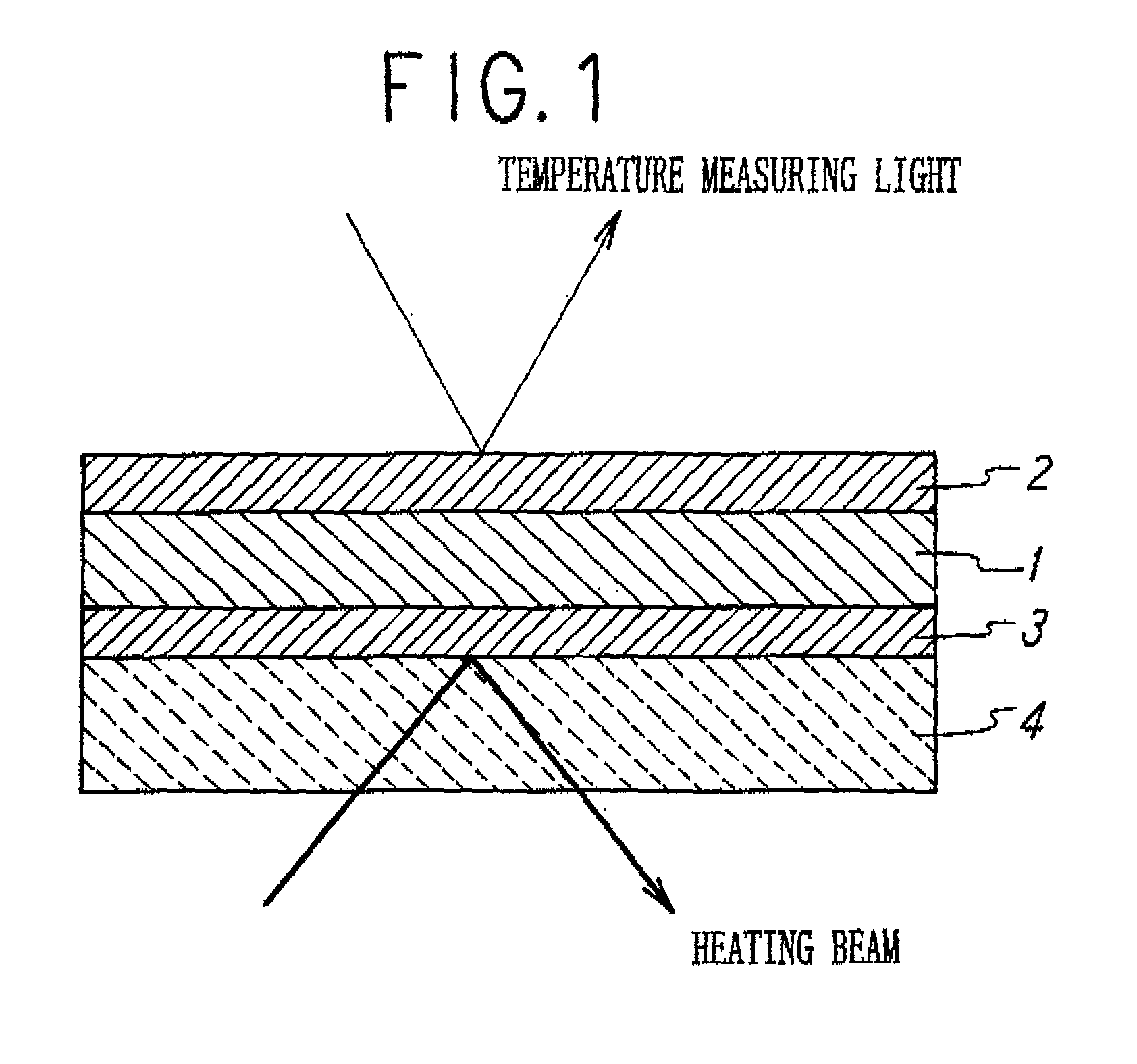
[0024] According to the present invention, when a thermal diffusivity of an object substance is to be measured, if the object substance is a non-metal substance such as a semiconductor, it is required to prepare a sample material in a manner as shown in FIG. 1. In detail, the sample material is a three-layer structure including a non-metal film 1 whose thermal properties are unknown, a first metal film 2 disposed on one side (an upper surface when viewed in FIG. 1) of the non-metal film 1, and a second metal film 3 disposed on the other side (a lower surface when viewed in FIG. 1) of the non-metal film 1. Here, the first and second metal films 2, 3 are the same identical substance whose thermophysical properties are known, and so formed that they have the same thickness when used in this manner. The three-layer structure is disposed on a transparent substrate 4. However...


PUM


Abstract

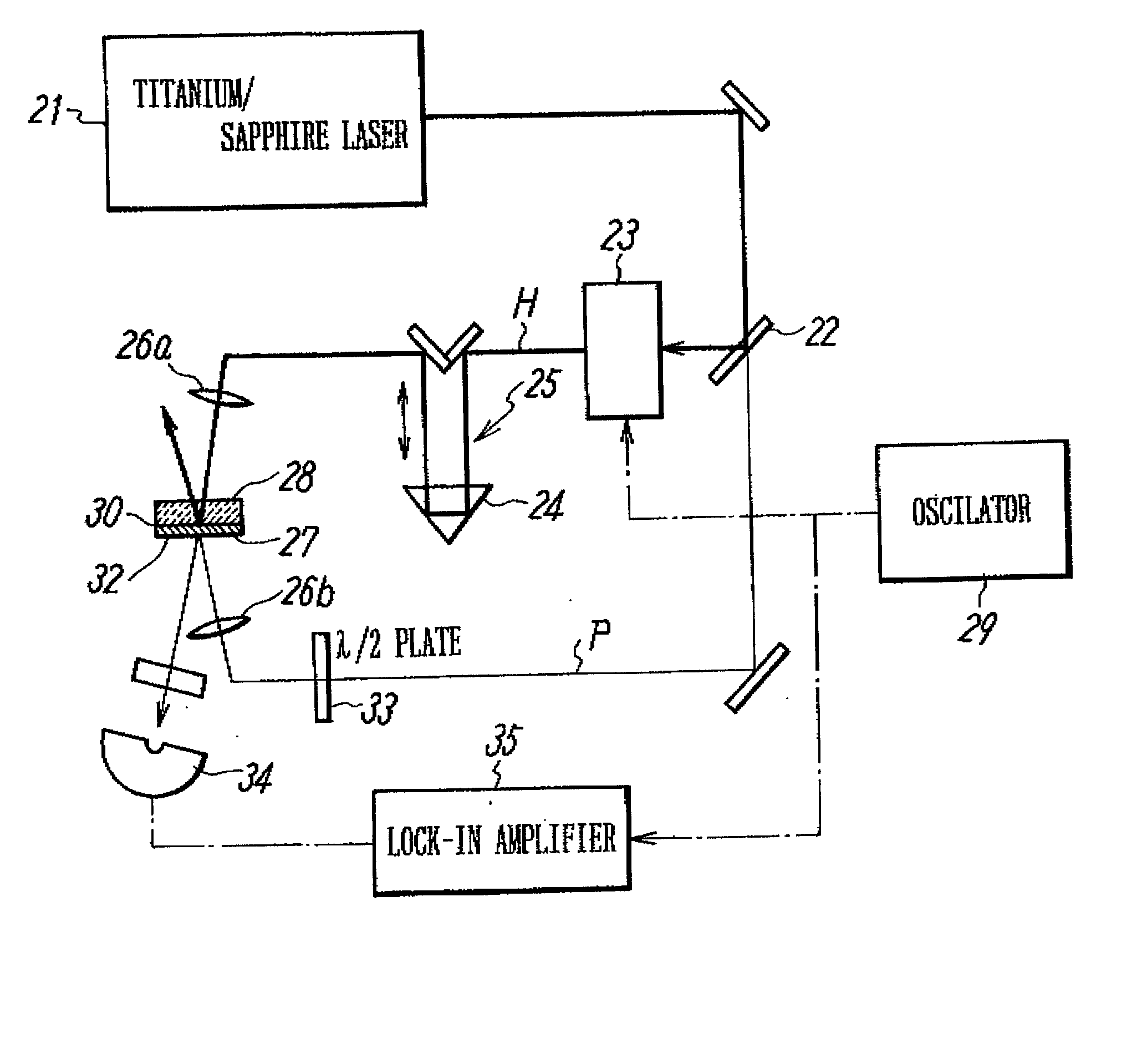
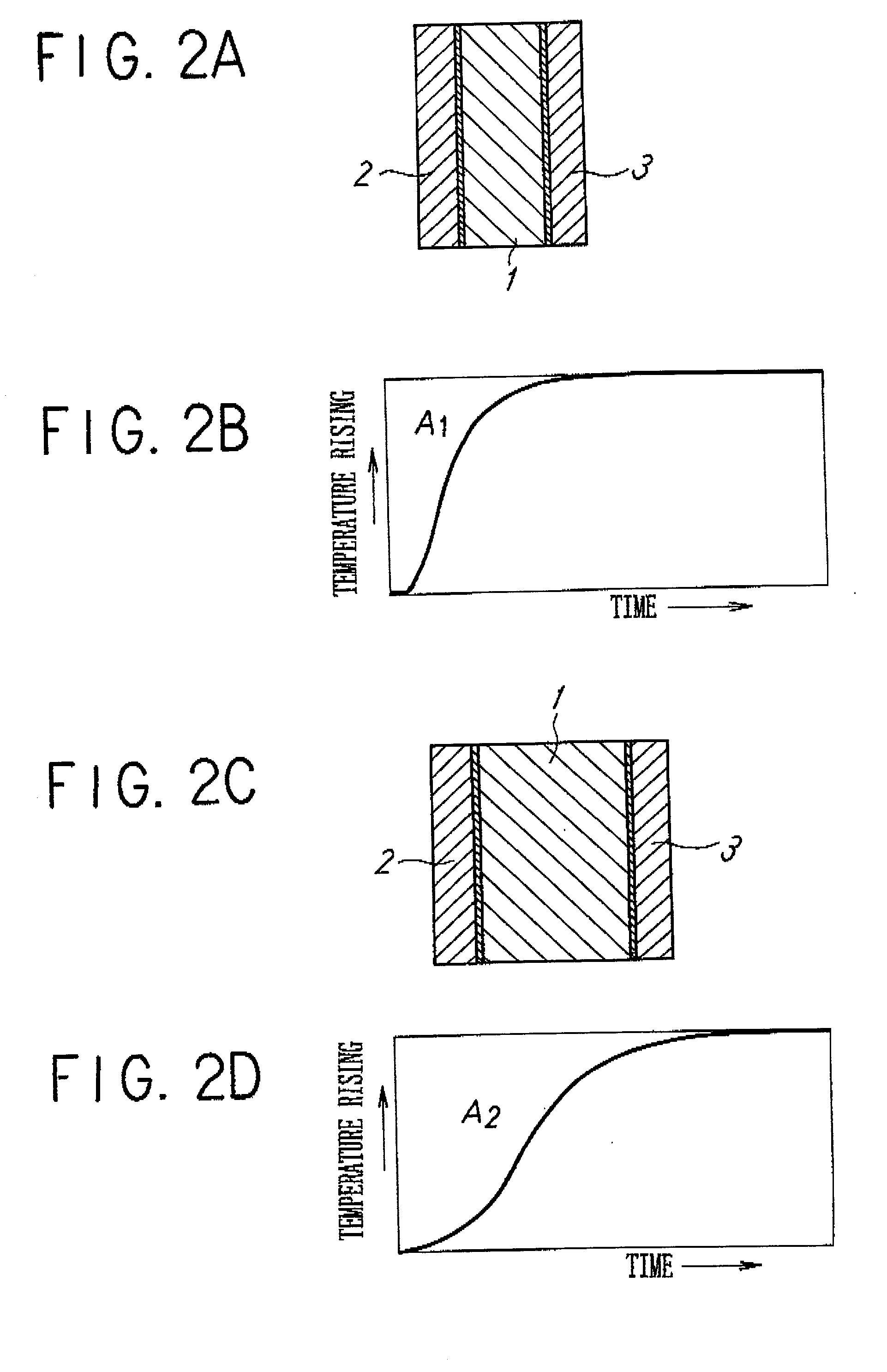
An object of the invention is to make it possible to correctly and easily measure a thermal diffusivity within a three-layer substance containing an non-metal substance. A non-metal film 1 whose thermophsical properties are unknown is disposed between a first metal film 2 and a second metal film 3, thereby forming a sample having a three-layer structure. The metal films 2 and 3 have predetermined known thermophsical properties, belong to the same sort of substance and have the same thickness. The three-layer substance is disposed on a transparent substrate 4 and is heated from below the second metal film 3, using a picosecond light pulse coming from below and passing through the transparent substrate 4. The light pulse used in the irradiation is converted into a heat in the second metal film 3 during only one picosecond, with such heat diffusing through interface / non-metal film layer / interface and thus arriving at the first metal film 2. By measuring a temperature change on the surface of the first metal film 2, it is possible to perform correct measurement by using the thermoreflectance method formerly suggested in a patent application by the inventors of the present invention.

Description

[0001] The present invention relates to a method for measuring a thermal diffusivity within a substance having a three-layer laminated structure. In particular, this invention relates to a method for measuring a thermal diffusivity and an interface thermal resistance, which method is suitable for correctly measuring a thermal diffusivity within a three-layer film structure containing a non-metal substance, such as a semiconductor device and an optical disc type data recording medium.[0002] 2. Description of Prior Art[0003] With regard to various technical fields, thin film technique is considered to be the most advanced technique and has attracted a considerable public attention. Particularly, thin film structure plays an important role in a highly integrated semiconductor device, DVD-RAM, MO and the like. Specifically, a multi-layered thin film structure has been put into practical use, so that analyzing the properties thereof has become an important task in this field. On the othe...

Claims


Application Information

Patent Timeline
IPC IPC(8): G01N25/18
CPCG01N25/18
Inventor BABA, TETSUYA
Owner NAT INST OF ADVANCED IND SCI & TECH
Learn More