
Method and apparatus of producing and utilizing thermal energy in a combined heat and power plant

a technology of combined heat and power plant, which is applied in the direction of steam use, mechanical equipment, machines/engines, etc., can solve the problems of system efficiency reduction, process steam demand may drop drastically, energy wastage occurs,

Active Publication Date: 2014-07-31
PALANISAMY KRISHNA MOORTHY
View PDF5 Cites 13 Cited by
  • Summary
  • Abstract
  • Description
  • Claims
  • Application Information

AI Technical Summary

Benefits of technology

The patent describes a method for regulating the output of vaporized secondary fluid in a vessel. The method involves increasing or decreasing the flow rate of the make-up fluid into the secondary space to control the output of the vaporized secondary fluid. This allows for better regulation of the pressure and temperature of the secondary fluid. The method also includes a control system to regulate the pressure and level of the secondary fluid in the vessel. The technical effects of this patent include improved control over the output of vaporized secondary fluid, reduced surplus or deficit flow of process steam, and better regulation of the hot water surface level in the vessel.

Problems solved by technology

a. Where the electrical generator is operated standalone and not paralleled with the utility grid, the primary control will be to maintain voltage and frequency where the electrical power output is matched with the electric load. This then determines the fluctuations in the quantity of thermal output as well as any excess or deficiency in thermal output to be compensated for. Conversely, vastly fluctuating thermal loads could occur, for example, when the thermal output is used for batch heating process systems or when the process is shutdown unscheduled. In the presence of the said such fluctuating thermal loads, a need then arises to regulate the heat supply to the thermal system and this is taken care of by installing a secondary control. If a deficiency in the process steam supply occurs, this is tackled by installing a steam bypass-reducing de-superheating system with high pressure steam source. If there is any surplus steam produced by the system, this is vented to the atmosphere or bypassed to a dump condenser and the condensate returned to the power circuit. Herein is where energy wastage occurs and system efficiency is reduced.
b. In contrast to (a) above, there may be cases where the electrical generator is not operated standalone, i.e. the electrical generator is operated connected to a grid. Here the primary control will be to control the exhaust steam pressure. The process steam demand dictates the electrical power of the turbine generator and any surplus or deficiency in exhaust steam supply is made up by adjusting the power flow to the grid. This necessitates the turbine drifting away from the design operation point of maximum efficiency. Sometimes the process steam demand may drop drastically for short periods in which event excess steam will be vented to the atmosphere or bypassed to a dump condenser to keep the electrical power system stable or to maintain a minimum supply to the grid, but this again wastes energy reducing system efficiency.
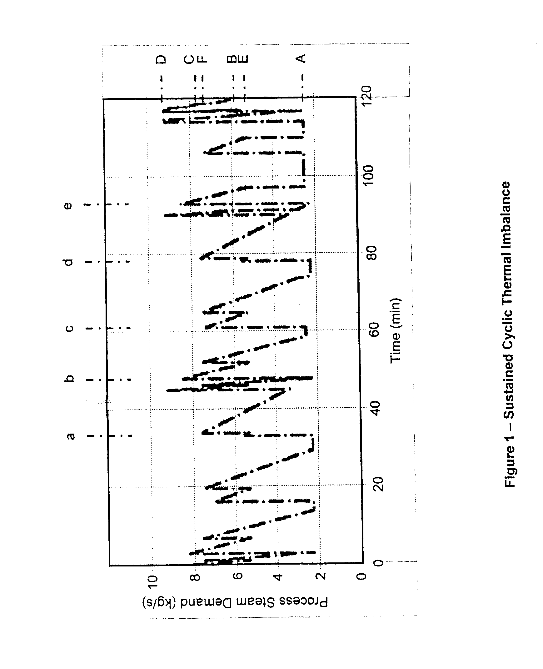
The challenge in practice is to achieve efficient and economic operation irrespective of rapid and substantial changes in electrical and thermal loads.
Simultaneously precipitous changes in thermal loads may take place as process heating plants are run up or shutdown and especially if batch processes are involved.
Venting off steam to the atmosphere to maintain stability is a common viability but this is a cause for a reduction in system efficiency and loss of pure water from the system.
Similarly, throttling high-pressure steam to make-up for a lower pressure steam used in low-temperature heating is also an inefficient use of thermal energy.
An adverse impact on the efficiency of the cogeneration system occurs when there is a change in the power-to-heat ratio which will then require an immediate response by way of either supplementary steam supply or power supply accordingly.
Where there is rapid and erratic variation of the process heat demand and this is left uncontrolled this could lead to consequential effects that ripple through to the boiler operation.
Erratic load on the boiler causes undue stress that may reduce its useful life span.
These are causes of potential thermal energy loss and corresponding fluid loses from the system.

Method used


Image

  • Method and apparatus of producing and utilizing thermal energy in a combined heat and power plant
  • Method and apparatus of producing and utilizing thermal energy in a combined heat and power plant
  • Method and apparatus of producing and utilizing thermal energy in a combined heat and power plant

Examples


Embodiment Construction

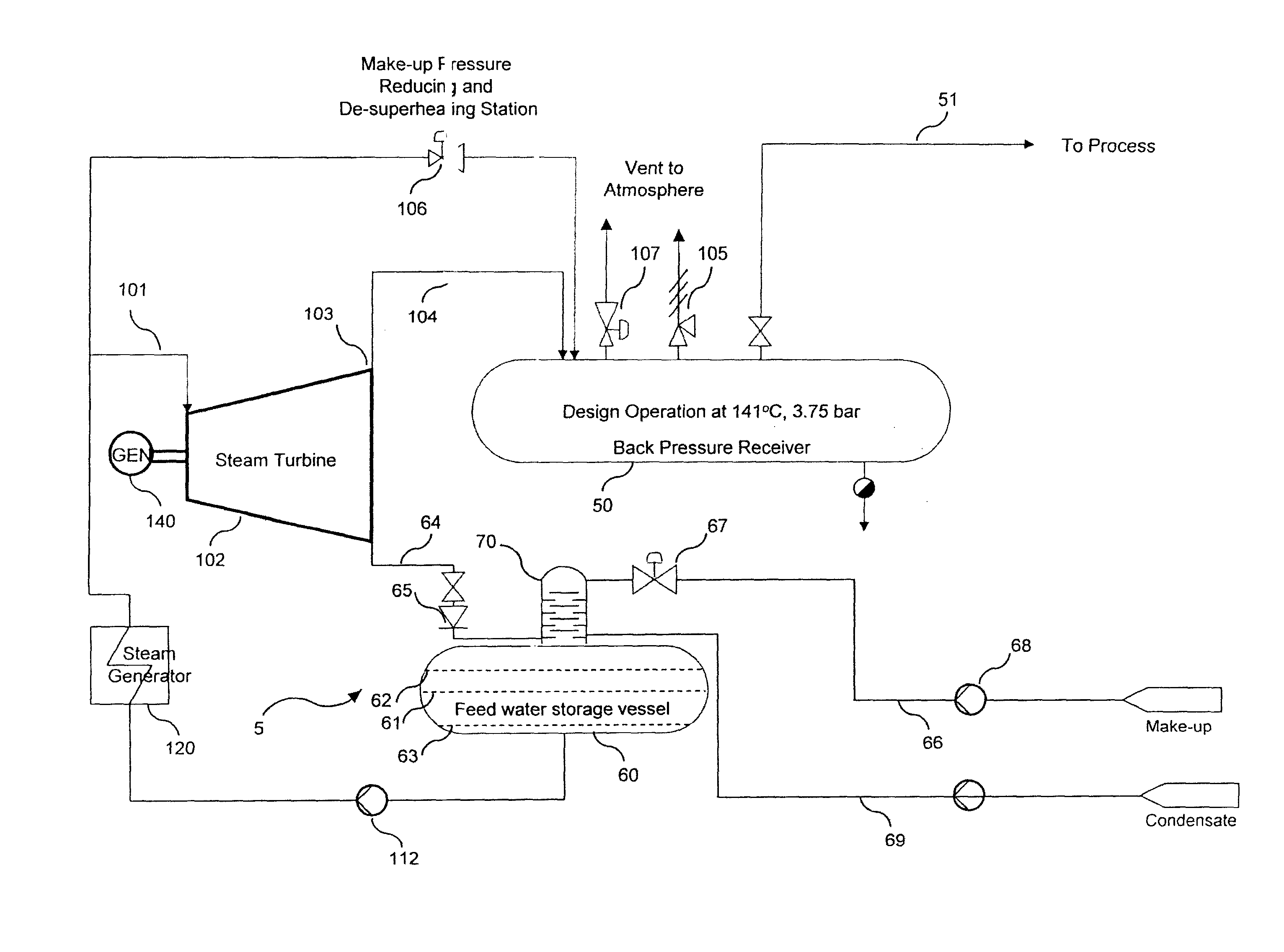
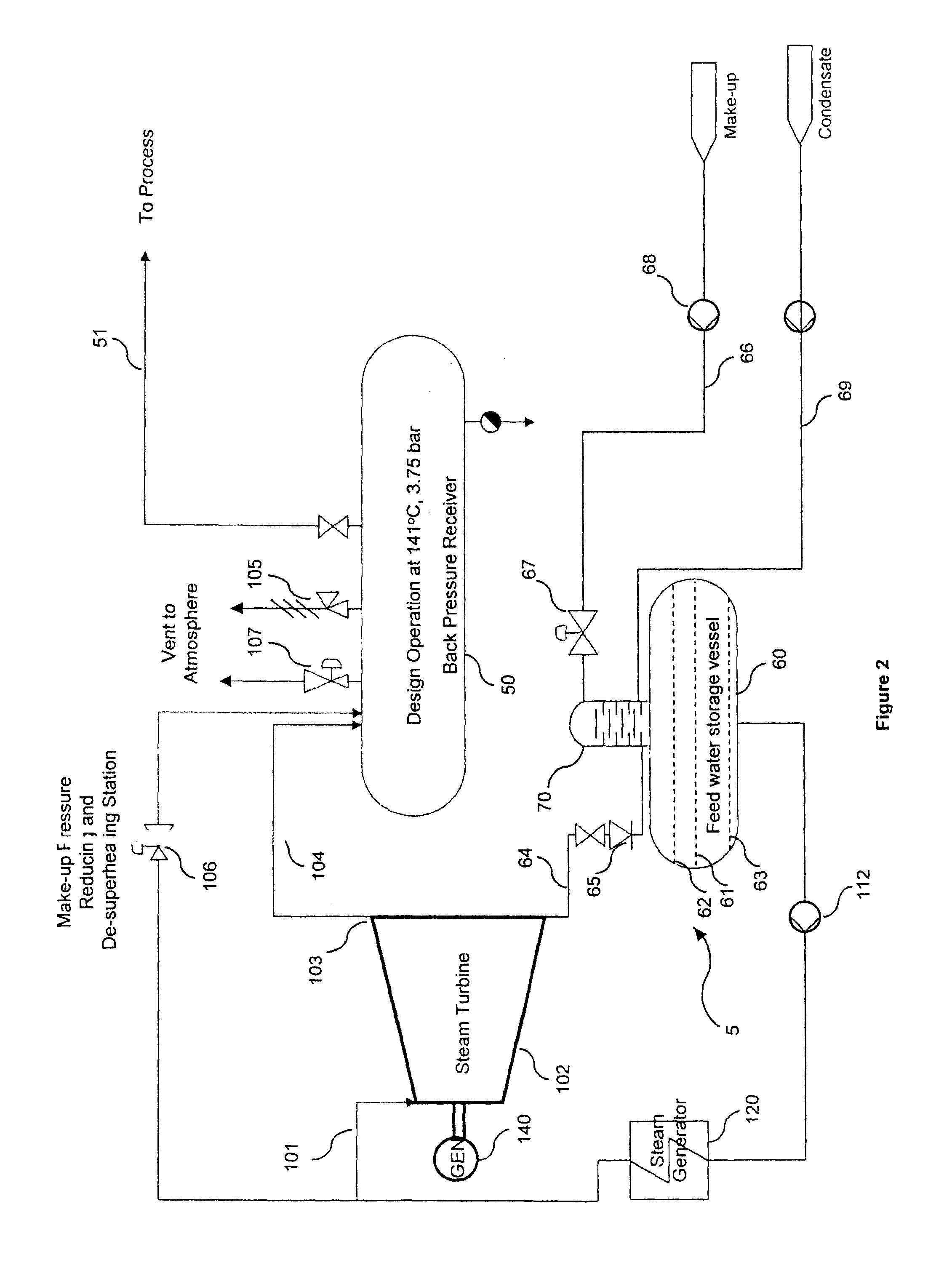
[0096]The invention is directed towards offering a solution to produce and utilize thermal energy in a combined heat and power (CHP) plant, more particularly in a palm oil extraction plant (or palm oil mill) with improved operational reliability, flexibility and energy efficiency.

[0097]Certain terminology will be used this description for convenience in reference only and will not be limiting.

[0098]In this description the term “surplus steam” or “surplus vaporized secondary fluid” refers a situation where the mass flow of the fluid at the supply source to a downstream process is in excess of the mass flow of fluid at admission into the downstream process with a tendency of pressure rise in the fluid supply conduit, and the term “deficit steam” or “deficit vaporized secondary fluid” refers to a situation where the mass flow of the fluid at the supply source to a downstream process is in shortage of the mass flow of fluid at admission into the downstream process with a tendency of pre...


PUM


Abstract

Method and apparatus for operating a combined heat and power system with greater flexibility, reliability, control and stability, for providing operational flexibility and energy efficiency in operating a combined heat and power plant which includes a backpressure steam engine that expands a high temperature heat source of a thermodynamic fluid to generate mechanical power and discharge its spent heat for a beneficial use comprises a vessel subsystem for the spent heat, said vessel subsystem including: at least one main indirect heat exchange device or vessel (7) in heat exchange communication between its primary space (10) and its secondary space (11). The present invention also discloses the use of a method and apparatus to operate a combined heat and power system.

Description

FIELD OF THE INVENTION[0001]The present invention relates to method and apparatus of producing and utilizing thermal energy in a combined heat and power plant.BACKGROUND[0002]Many Combined Heat and Power (CHP) systems also known as cogeneration are installed and operating in different process industries to provide electrical power and thermal energy. One of the most common versions uses a steam turbine to output mechanical shaft power that drives an electrical generator to produce electricity. Concurrently, during this mechanical power generation, the spent heat from the steam turbine exhaust is supplied as thermal energy either directly in the form of steam or hot water or hot air for a beneficial use. The thermal energy can be used for a myriad of applications, including process heating and for cooling applications using an absorption chiller.[0003]Tied to the above, there are two typical scenarios of operation which can lead to operational inflexibility, wastage of energy and red...

Claims


Application Information

Patent Timeline
Patent Type & Authority Applications(United States)
IPC IPC(8): F01K3/08F01K17/02
CPCF01K3/004F01K3/262F01K17/02Y02E20/14F01K3/08F01K23/04C11B1/16F01K17/00Y02P80/15
Inventor PALANISAMY, KRISHNA MOORTHY
Owner PALANISAMY KRISHNA MOORTHY
Learn More