
Installation and methods for storing and restoring electrical energy using a piston-type gas compression and expansion unit

A return device and gas compression technology, which is applied in the field of storage and return electric energy devices, can solve problems such as excess

Active Publication Date: 2010-09-08
SAIPEM SPA
View PDF1 Cites 14 Cited by
  • Summary
  • Abstract
  • Description
  • Claims
  • Application Information

AI Technical Summary

Problems solved by technology

[0014] The problem that arises is storing electrical energy from conventional power generating stations such as coal, gas, oil or nuclear plants in order to be able to return very quickly large amounts of energy to the grid during peak periods when energy demand exceeds production
[0015] Also, with renewable energy such as wind turbines or seawater turbines, the problem is being able to store large amounts of energy during periods of strong winds or currents, which corresponds to excess production, so that during periods in which production is insufficient i.e. when wind or currents Inability to maintain the generation level at the minimum threshold during which the energy is returned

Method used


Image

  • Installation and methods for storing and restoring electrical energy using a piston-type gas compression and expansion unit
  • Installation and methods for storing and restoring electrical energy using a piston-type gas compression and expansion unit
  • Installation and methods for storing and restoring electrical energy using a piston-type gas compression and expansion unit

Examples


Embodiment Construction

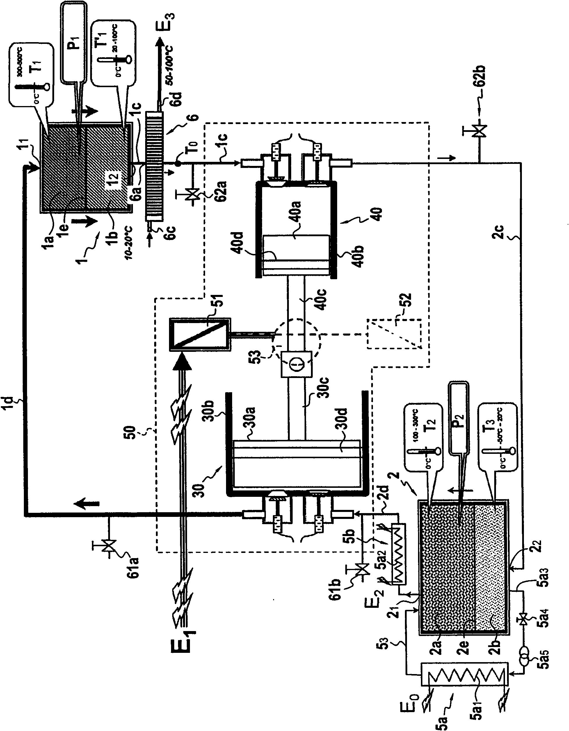
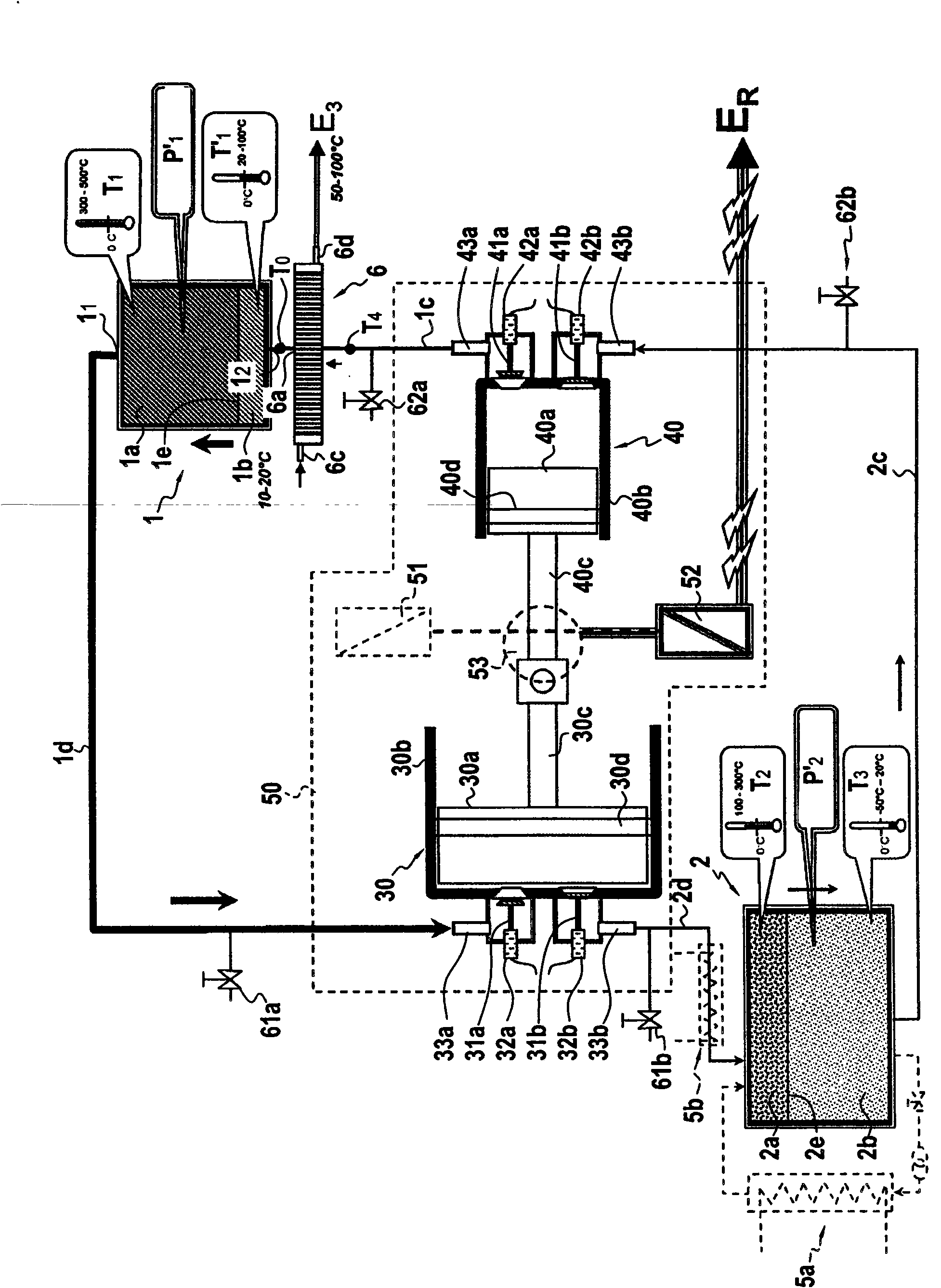
[0101] The inventive device for storing electrical energy and for returning electrical energy comprises:

[0102] a first thermally insulated enclosure 1 comprising steel walls 10 mm to 100 mm thick and filled with a first porous refractory material capable of resisting the high temperature and pressure of the inert gas contained therein, wherein the temperature T1 is in the range of 300°C to 1000°C and more particularly at 400° C. and a pressure P1 in the range of 50 bar absolute pressure (bara) to 300 bara (ie in the range of 5 MPa to 30 MPa); and

[0103] ● A second thermally insulated enclosure 2, with the same volume, eg located at 1000m 3 to 5000m 3 In the range of 10mm to 100mm, the steel wall has a thickness in the range of 10mm to 100mm and is filled with a second porous refractory material capable of resisting the temperature T2 and pressure P2 of the inert gas contained therein, that is, T2 is between 100°C and 500°C °C and more particularly about 250 °C.

[0104...


PUM


Abstract

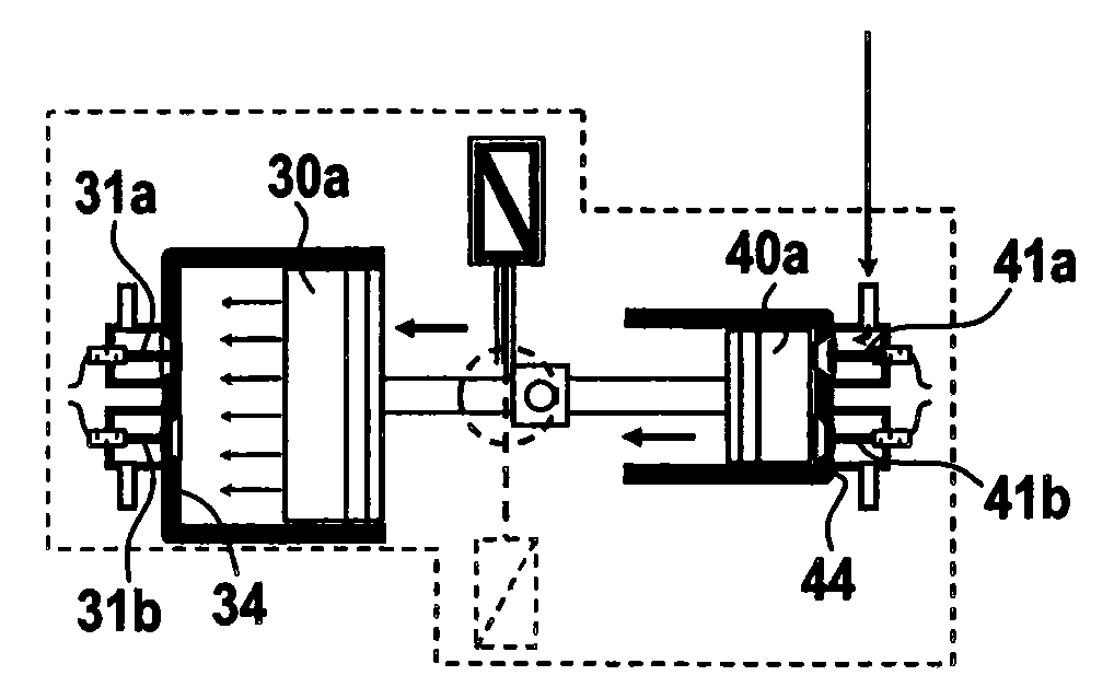
The present invention relates to installations and methods for storing and restoring electrical energy comprising two, a first and a second, lagged chambers (1,2) containing porous refractory materials (11) through and between which a gas is circulated by causing the gas to circulate through two, a first and a second, compression / expansion sets (30, 40) interposed in the circuit of pipework (1c, 1d, 2c, 2d) between the upper ends (11, 21) and, respectively, lower ends (12, 22) of said first and second chambers, each compression / expansion set comprising a piston (30a, 40a) to which there is imparted a translational movement in a cylinder (30b, 40b), each set operating in a different mode, either in compression mode or in expansion mode, one of the two compression / expansion sets receiving a gas at a higher temperature than the other set such that, in compression mode, it is operated by an electric motor (41) which consumes electrical energy that is to be stored E1, and in thermodynamic engine mode it operates an electric generator (52) able to restore electrical energy (ER). The electrical energy is stored in the form of heat in masses of refractory products, and this stored thermal potential energy is restored in the form of electrical energy.

Description

technical field [0001] The present invention relates to a device for storing and returning electrical energy suitable for storing tens to hundreds of megawatt-hours (MWh), and it also relates to a method in which the device of the invention is used to store electrical energy in the form of heat, and a for returning electrical energy (E R )Methods. Background technique [0002] The invention relates to storing energy at high temperatures and in particular to storing electrical energy to return it from the grid at times of peak consumption. [0003] Electricity is typically generated by power stations using various fuels such as gas, oil, coal or lignite to generate energy. Another approach is to use nuclear fuel to generate heat, which is then converted into electricity in a high-pressure steam turbine. [0004] Renewable energies are also known in various countries which can contribute to a large extent to the production of electricity. Among other possibilities, mention...

Claims


Application Information

Patent Timeline
Patent Type & Authority Applications(China)
IPC IPC(8): H02J15/00F01K3/12F28D20/00
CPCF01K3/12F01K7/36F28D20/0056F28D17/02F01K25/00Y02E60/142F02G1/044Y02E60/14
Inventor J·吕埃
Owner SAIPEM SPA
Learn More