

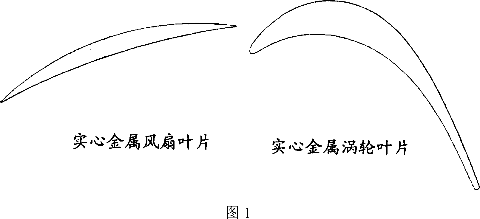
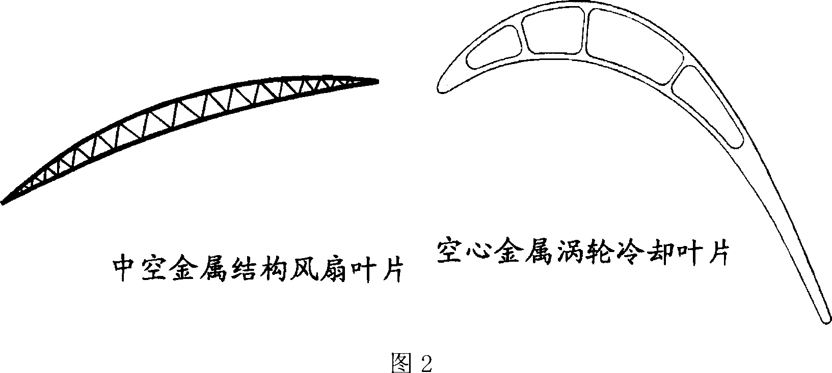
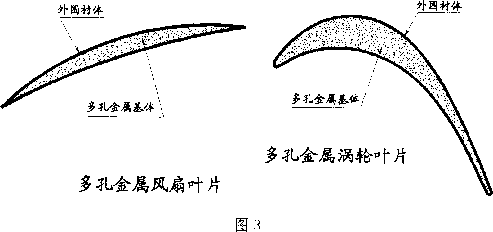
Porous metal vane coupling design method
A design method and porous metal technology, applied in the direction of supporting elements of blades, mechanical equipment, components of pumping devices for elastic fluids, etc., can solve the problems of difficult processing, low yield, complex process, etc., and achieve improved Effects of performance and service life, improvement of specific strength, and reduction of cooling air volume
- Summary
- Abstract
- Description
- Claims
- Application Information
AI Technical Summary
Problems solved by technology
Method used
Image

Examples
Embodiment 1
[0014] Embodiment 1: The method is used in the design process of the blade of turbomachinery, which includes the following steps:
[0015] 1) Perform blade aerodynamic design;
[0016] 2) select the porosity to carry out the design of the sandwich body of the porous metal blade;
[0017] 3) Conduct strength and vibration analysis on porous metal blades;
[0018] 4) Processing the sandwich body;
[0019] 5) Process the outer lining of the blade;
[0020] 6) Check and check the porous metal blade, and repeat the above steps until the design is completed.
Embodiment 2
[0021] Embodiment 2: the method is used for the design process of fan or compressor blade, and it comprises the steps:
[0022] 1) Carry out the aerodynamic design of the fan / compressor blade, and obtain the velocity triangle, aerodynamic parameters, stage parameters and total parameters of each blade outlet along the radial section according to the overall performance requirements of the aero-engine / gas turbine; then complete the blade type Surface modeling and airfoil stacking, and finally the design results obtained through the calculation and analysis of the full three-dimensional viscous flow field are checked. If the requirements are not met, the above process is repeated until the aerodynamic performance requirements are met; Styling means to achieve advanced aerodynamic performance indicators;
[0023] 2) The fan or compressor blade that step 1) is obtained is carried out the analysis of solid metal blade intensity, according to strength analysis result, select porosit...
Embodiment 3
[0028] Embodiment 3: the method is used for the design process of turbine blade, and it comprises the steps:
[0029] 1) Carry out the aerodynamic design of the turbine blades, and obtain the velocity triangle, aerodynamic parameters, stage parameters and total parameters of each blade outlet along the radial section according to the overall performance requirements of the components of the aero-engine / gas turbine; then complete the blade surface modeling, The airfoils are stacked, and finally the design results obtained through the calculation and analysis of the full three-dimensional viscous flow field are checked. If the requirements are not met, the above process is repeated until the aerodynamic performance requirements are met; The aerodynamic performance index;
[0030] 2) Analyze the blade cooling and heat transfer characteristics of traditional metal materials for the blade obtained in step 1). According to the required blade cooling efficiency, design the porosity d...
PUM
 Abstract
Description
Claims
Application Information