Computer mouse with specialized button(s)

a mouse and mouse technology, applied in computing, instruments, electric digital data processing, etc., can solve the problems of not having a very accurate rotatable ball, optical or other surface tracking arrangement for pointing/cursor control, devices without rotatable balls, and other problems, to achieve the effect of optimum rotatable wheel as scroll controller

Inactive Publication Date: 2002-07-04
ARMSTRONG BRAD A
View PDF58 Cites 72 Cited by
  • Summary
  • Abstract
  • Description
  • Claims
  • Application Information

AI Technical Summary

Problems solved by technology

In contrast, pointer control on hand supported computer control devices, sometimes referred to as remote controllers or remote mice such as sold by Interlink Electronic, Inc. of Camarillo, Calif., USA, are operable via a variable speed pointer control button (and possibly scroll control buttons), yet such devices do not contain the very accurate rotatable ball, optical or other surface-tracking arrangement for pointing/cursor control, thus such devices having no rotatable ball, optical surface-tracking or other surface-tracking arrangement for pointing control are considered inferior.
Another type of electrical sensor employed on mice for scrolling control is a rotary encoder type such as a rotary optical encoder functional with a bi-directionally rotatable exposed wheel as described in U.S. Pat. No. 5,530,455 issued Jun. 25, 1996 to W. G. Gillick. The Gillick prior art rotatable scroller wheel is not considered an optimal interface between a human digit and electrical sensor because of the unfamiliar or non-conventional rotatable aspect requiring a finger motion substantially different than a depressible button, and further because of the rather high cost of optical encoders, and additionally the rotatable wheel is not optimum as a scroll controller for moderate to high speed scrolling because scrolling speed is determined by wheel rotation speed, and high wheel rotation speed is difficult to achieve by finger manipulation.
Furthermore, in a low cost mouse, additional high cost optical encoders may be cost prohibitive.
The Gilligan et al lever-actuated scroll control is considered less than optimal because of the high costs of optical encoders and because of the un-familiar and awkward nature of a thumb lever positioned extending outward from a side of the mouse housi...

Method used


Image

  • Computer mouse with specialized button(s)
  • Computer mouse with specialized button(s)
  • Computer mouse with specialized button(s)

Examples


Embodiment Construction

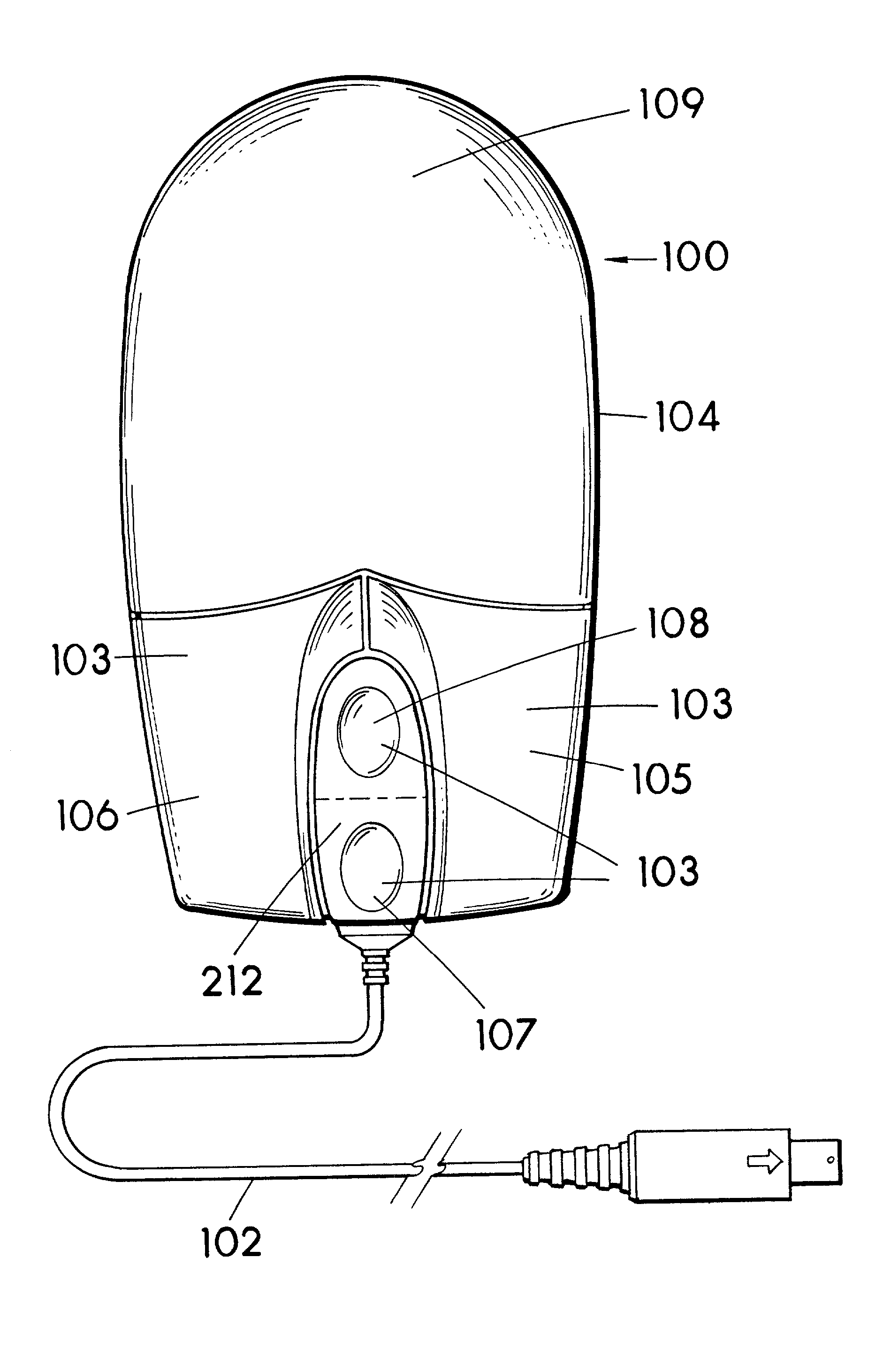
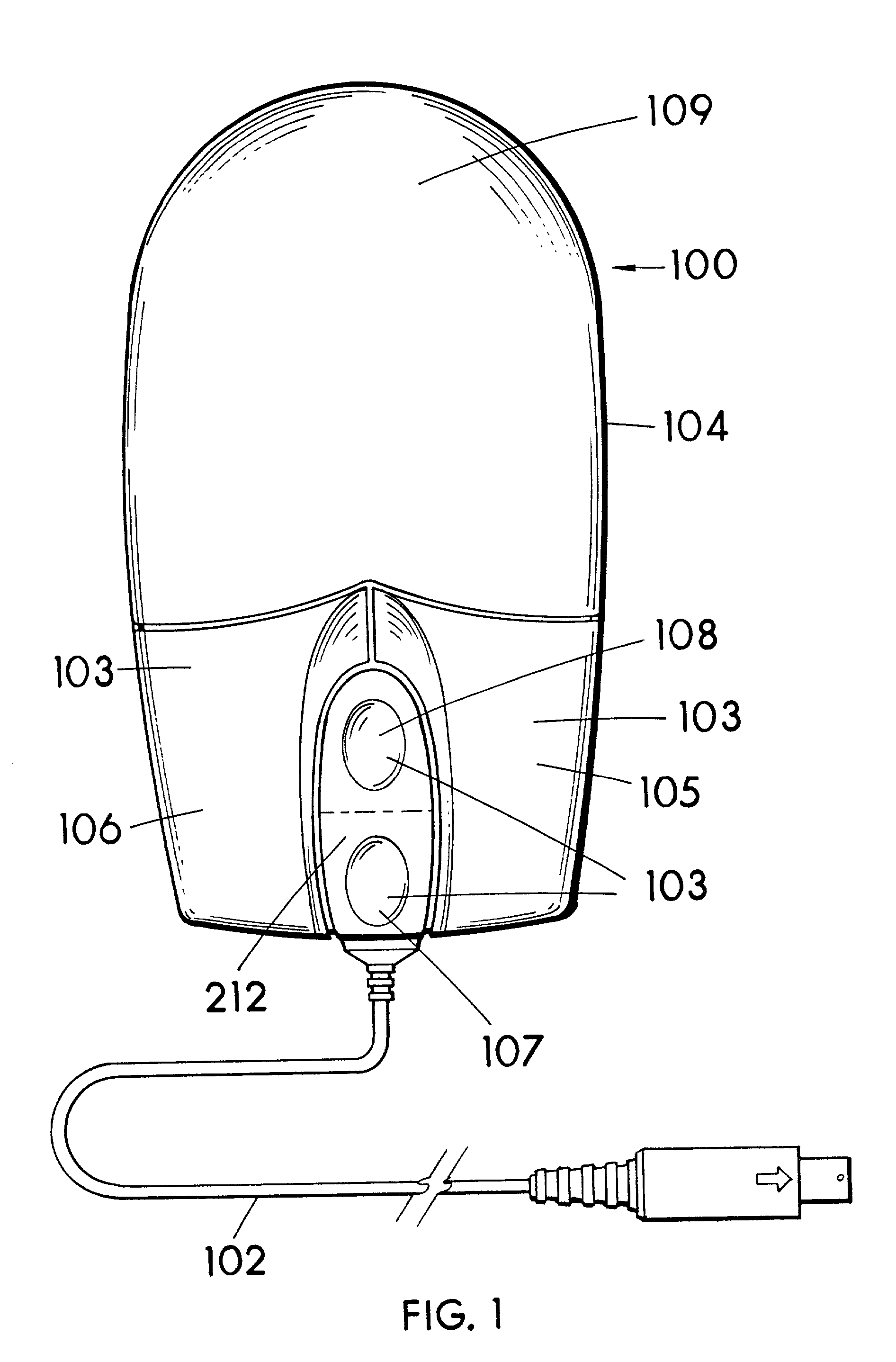
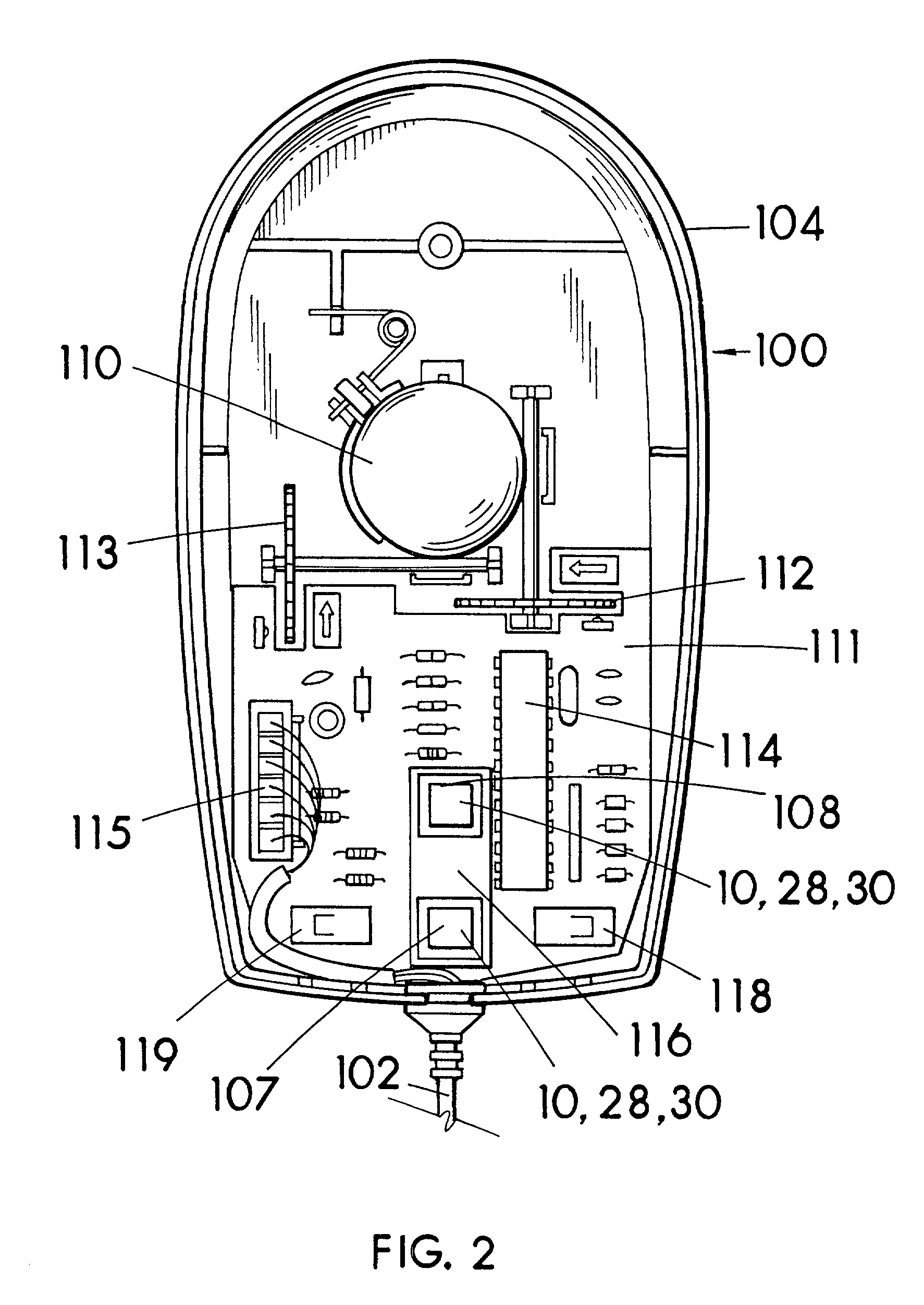
[0058] In elaboration of the hereinabove details of the Invention and with specific reference to the included drawings, best modes for carrying out the invention will now be further described. FIG. 1 is a top plan view of a desktop operated computer control device, i.e., mouse 100 with a plurality of finger depressible surfaces or buttons 103 on a single depressible plate 212 exposed on a top of the housing 104 top portion, and including a rotatable pointer control ball 110 (FIG. 2). Desktop mouse 100 physically appears as some prior art desktop mice, yet is in accordance with the present invention, although the improved desktop mouse as taught herein can be shaped into different appearances including different button 103 layouts. Desktop mouse 100, with the exception of the electronic circuity particulary for reading scroll buttons 107 and 108, is conventionally structured much like some prior art desktop mice of the type having rotatable pointer control balls, right and left selec...


PUM


Abstract

A computer control mouse including a housing, electronic circuitry within the housing, surface-tracking pointing control, i.e, ball or optical, a plurality of finger depressible buttons exposed on the housing and interfacing with sensors electrically connected with the circuitry. Some of the finger depressible buttons are for user selection of signals to be sent to the computer/software for variable rate window or screen scroll control. Some of the buttons are for communicating command signals to software, the signals activating display of information of a previously visited network address either Back or Forward, dependant on the mouse button, the activating of display of information of the previously visited network address with the mouse button occurring without a requirement of a pointer having to be located on a Back or Forward software shown button on the display.

Description

[0001] A 35 USC 120 priority claim is hereby made to my pending U.S. non-provisional application Ser. No. 09 / 167,314 filed Oct. 6, 1998, now U.S. Patent (to be filled in later).[0002] 1. Field of the Invention[0003] The present invention relates to control devices such as a computer mouse. The invention is directed toward a mouse of the type having for pointing control, preferably surface-tracking pointer control, and which further includes depressible buttons which can be depressed for scrolling, back and forward functions in Windows or the like.[0004] 2. Description of the Related Prior Art[0005] Prior art surface-tracking control devices for pointing control and for controlling certain functions of computers, such as the mouse type control device, have been used for years, the structures of which and means for interfacing with computers and computer programs and the like being well understood by those skilled in the art.[0006] A typical prior art computer mouse comprises a housin...

Claims


Application Information

Patent Timeline
IPC IPC(8): G06F3/038
CPCG06F3/03543G06F3/038G06F3/0383
Inventor ARMSTRONG, BRAD A.
Owner ARMSTRONG BRAD A
Why Eureka
Try Eureka