Computerized repetitive-motion exercise logger and guide system

a technology of repetitive motion and logging system, which is applied in the field of collecting athletic performance data, can solve the problems of difficult to collect performance data of one's exercise regime without an extra person, tedious manual record-keeping, and the inability to meet the needs of a single person, and achieves the effect of reducing the number of times of recording

Inactive Publication Date: 2002-07-04
WARNER RICHARD D
View PDF0 Cites 59 Cited by
  • Summary
  • Abstract
  • Description
  • Claims
  • Application Information

AI Technical Summary

Problems solved by technology

Prior to this invention it has been difficult to collect performance data of one's exercise regime without an extra person and tedious manual record-keeping.
Some "traditional" techniques may under close scrutiny be determined to be ineffective or not optimally effective for a given individual.
Currently even the most disciplined record-keeping athletes must largely depend on subjective opinion as to what constitutes their best workout regiment, because they do not do the math and it takes a lot of time to create useful graphs of data.
This detracts from the athletes concentration and has the same limitations for analysis of requiring mathematics performed to compute work and power metrics, and requiring manual input into a computer.
This approach has limited flexibility and is complicated to implement.
Typically a network of transmitters or terminals must exist (complicated) and it is hard to apply the approach generically to any given exercise station (less flexible)--the designs tend to be specific for one task, such as running.
None of the approaches embed small, simple, cheap, magnets along the running track to work with the same generic logging system that is used for other types of exercise stations.
This approach also limits flexibility because the exercise equipment must be modified.
Once again, this limits flexibility because the device takes time to setup the network or make changes to it, plus it is more complicated and more expensive than having one unit that moves from station-to-station with you.
Another approach, taken by U.S. Pat. No. 5,947,869 to Shea Sep. 7, 1999 allows for a computerized exercise station to accept customized programs for an individual, but once again this approach only works with exercise equipment especially designed for it (limited flexibility).
The additional wires and sensors attaching to the athlete may be a distraction.
In general, the requirements for collecting work and power data for generic exercise repetitions had not currently been met.
For example, an audio tone may be generated every three seconds, but the device does not know when the user has completed the desired repetitions.
The device cannot tell the user he / she needs to speed up or slow down.
Another limitation of many existing sensor approaches is their range.
Other approaches add features that substantially increase cost and complexity but add little or nothing to the collection of the basic work and power performance data.
This requires a lot of memory, and expensive voice-recognition circuitry, when a modest sensor circuit will do the same thing.
This limits flexibility once again, and is not a generic approach.
That approach adds complexity and cost.
Numerous factors tend to reduce this range in practice, but it still has a range of several feet.

Method used


Image

  • Computerized repetitive-motion exercise logger and guide system
  • Computerized repetitive-motion exercise logger and guide system
  • Computerized repetitive-motion exercise logger and guide system

Examples


Embodiment Construction

FIG. 1, Software Pseudocode Listing

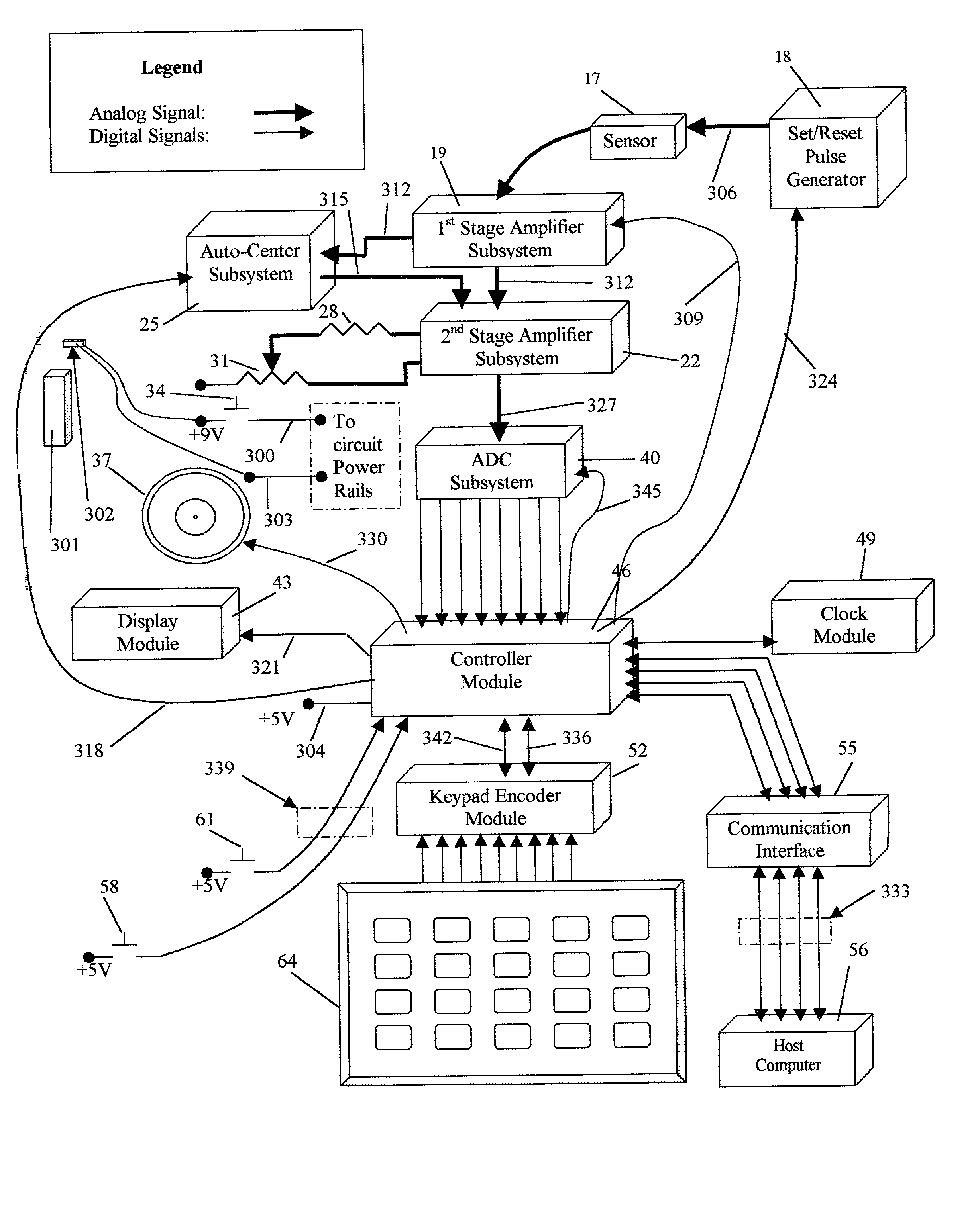
[0219] As can be seen in FIG. 1, the controller module 46 is the core of the system. The controller module and its software program provide a controller means for coordinating interactions between several other logical groups of components. The particular controller module used in this embodiment is a Basic STAMP IIE produced by Parallax, Incorporated.

[0220] The controller module also contains an integrated memory which is comprised of an integrated data memory for storing logged data and an integrated routine memory for storing preprogrammed exercise routines and user profile data. This is provided by 16K of online EEPROM.

[0221] The company Parallax, Incorporated provides a development environment for their controller module. The development environment is used on a host computer to write the programs in a language called PBASIC. The programs are then downloaded to the controller module 46 via the communication interface 55. A built-in interpreter...


PUM


Abstract

This system includes a self-contained, non-invasive system for collecting work and power performance data on nearly any kind of repetitive-motion exercise. See the glossary for definitions of terms used in this specification. It is non-invasive in that no permanent modifications need made to existing exercise equipment. It is a battery-powered system that remotely senses iterations of a moving part or body member, and records them with a time-stamp. It also records weight and distance of travel if they are input-but for some exercises this function may be deemed not necessary, or ignored. If time, weight, and distance are known then work and power metrics can be calculated on the data when it is analyzed on a host computer. This data can then be graphed to provide comparisons from workout session to workout session. The user can detect trends, and differences in performance as workout variables are manipulated. Workout variables include, but are not limited to: weight, distance of travel, time, order of exercise stations, number of sets, number of repetitions per set, pattern of weight increase / decrease for a given exercise station over the sets, pattern of extension and contraction per repetition, etc.

Description

CROSS-REFERENCES TO RELATED APPLICATIONS[0001] None. No provisional application was filed.[0002] 1. Field of Invention[0003] This invention relates to collecting athletic performance data, specifically to an improved logging and pacing system that generically works with most exercises.[0004] 2. Description of Prior Art[0005] Prior to this invention it has been difficult to collect performance data of one's exercise regime without an extra person and tedious manual record-keeping. It is desirable to be able to quantify one's power and ability to do work, and monitor trends over time. This can be manually accomplished by a person with a clipboard writing down weights, and distances for each set plus times for each repetition in the set of a given weight routine. The trainer must then type it all into a computer and graph or analyze it there. For running, a person or persons with stop-watches is required. It is desirable to be able to represent such data visually in graphs in calculate...

Claims


Application Information

Patent Timeline
Patent Type & Authority Applications(United States)
IPC IPC(8): A63B24/00A63B69/00A63B71/06
CPCA63B24/0021A63B24/0062A63B71/0605A63B71/0686A63B2024/0012A63B2024/0025A63B2024/0068A63B2220/13A63B2220/17A63B2220/30A63B2220/40
Inventor WARNER, RICHARD D.
Owner WARNER RICHARD D
Why Eureka
Try Eureka