Switchgear cabinet with an air-conditioning device

a technology of air-conditioning device and switchgear cabinet, which is applied in the direction of heat production device, indirect heat exchanger, light and heating apparatus, etc., can solve the problem of relatively large energy consumption of air-conditioners of this typ

Inactive Publication Date: 2002-07-11
RITTALWERK RUDOLF LOH GMBH & CO KG
View PDF0 Cites 23 Cited by
  • Summary
  • Abstract
  • Description
  • Claims
  • Application Information

AI Technical Summary

Benefits of technology

[0008] In connection with the underground heat exchanger, use is made of a relatively constant temperature level (6.degree. C. to 11.degree. C.) which prevails in the ground, starting at a depth of approximately 1 m. Because the ground has a large storage capacity, particularly if it is moist, this heat storage can be effectively used for cooling the switchgear cabinet. Therefore, during summer operations of the switchgear cabinet and with permissible internal temperatures of, for example, 45.degree. C., there is an approximate temperature difference of 34.degree. Kelvin available to the underground heat exchanger. It is easily possible to achieve a high cooling output with this arrangement. In winter, when the temperature conditions are reversed, it is possible with a permissible internal temperature of 0.degree. C. to utilize a temperature difference of, for example, 6.degree. Kelvin for the underground heat exchanger. In this mode the underground heat exchanger operates as a heater.
[0009] The air contained in the interior of the switchgear cabinet can be conveyed by the underground heat exchanger. However, it is also possible to conduct various fluids through the underground heat exchanger. Accordingly, particular gases or liquids can be conveyed. An interior heat exchanger is assigned to the interior of the switchgear cabinet, particularly if gases or liquids are used. The fluid coming from the underground heat exchanger then circulates through this interior heat exchanger. For improving its efficiency, it is then possible to assign a fan to the heat exchanger.
[0011] In accordance with one preferred embodiment of this invention, the underground heat exchanger is embodied as a flexible plastic pipe. This entire plastic pipe can be placed into the ground in a simple and time-saving manner. It is thus possible to provide the outlet line and the inlet line connected in one piece with the underground heat exchanger and conducted as far as the area of the interior of the switchgear cabinet. This outlet line and the inlet line are connected to pipe connector elements leading into the interior of the switchgear cabinet. Because the outlet and the inlet lines are embodied as one piece with the underground heat exchanger, no additional assembly and parts outlay is required. It is possible to conduct the plastic pipe as far as the area of the interior of the switchgear cabinet, or it can be connected with appropriate pipe connectors.
[0014] In accordance with one embodiment of this invention, at least one fan is assigned to the inlet line and / or the outlet line. The use of one or several fans makes a less noisy operation of the air-conditioner possible. This is possible if the interior of the switchgear cabinet is surrounded by a switchgear cabinet body, and each fan is housed in the interior of the switchgear cabinet. In this case no noise-generating elements of the air-conditioner are present outside the switchgear cabinet, such as is normally required with air-conditioners. The fans require relatively little electrical energy. In particular, the fans can be designed as direct current fans, which are directly supplied by a battery assigned to the interior of the switchgear cabinet.
[0017] With this, depending on the design of the seal of the bottom group, moisture can be prevented from entering the interior of the switchgear cabinet. In some applications, the seal prevents rodents, for example, from entering the interior of the switchgear cabinet.
[0018] In accordance with this invention, the inlet lines and the outlet lines are closed off at the switchgear cabinet by air-permeable covers. This prevents objects, for example tools, from falling into the underground heat exchanger during assembly in the interior of the switchgear cabinet. This also prevents rodents, which can enter the pipe area of the underground heat exchanger, from also entering the interior of the switchgear cabinet.

Problems solved by technology

Air-conditioners of this type have a relatively large energy consumption.
If switchgear cabinets are placed in outside areas, batteries are often required for supplying current because of the lack of electrical connections, which must be maintained at regular intervals and possibly recharged.

Method used


Image

  • Switchgear cabinet with an air-conditioning device
  • Switchgear cabinet with an air-conditioning device

Examples


Embodiment Construction

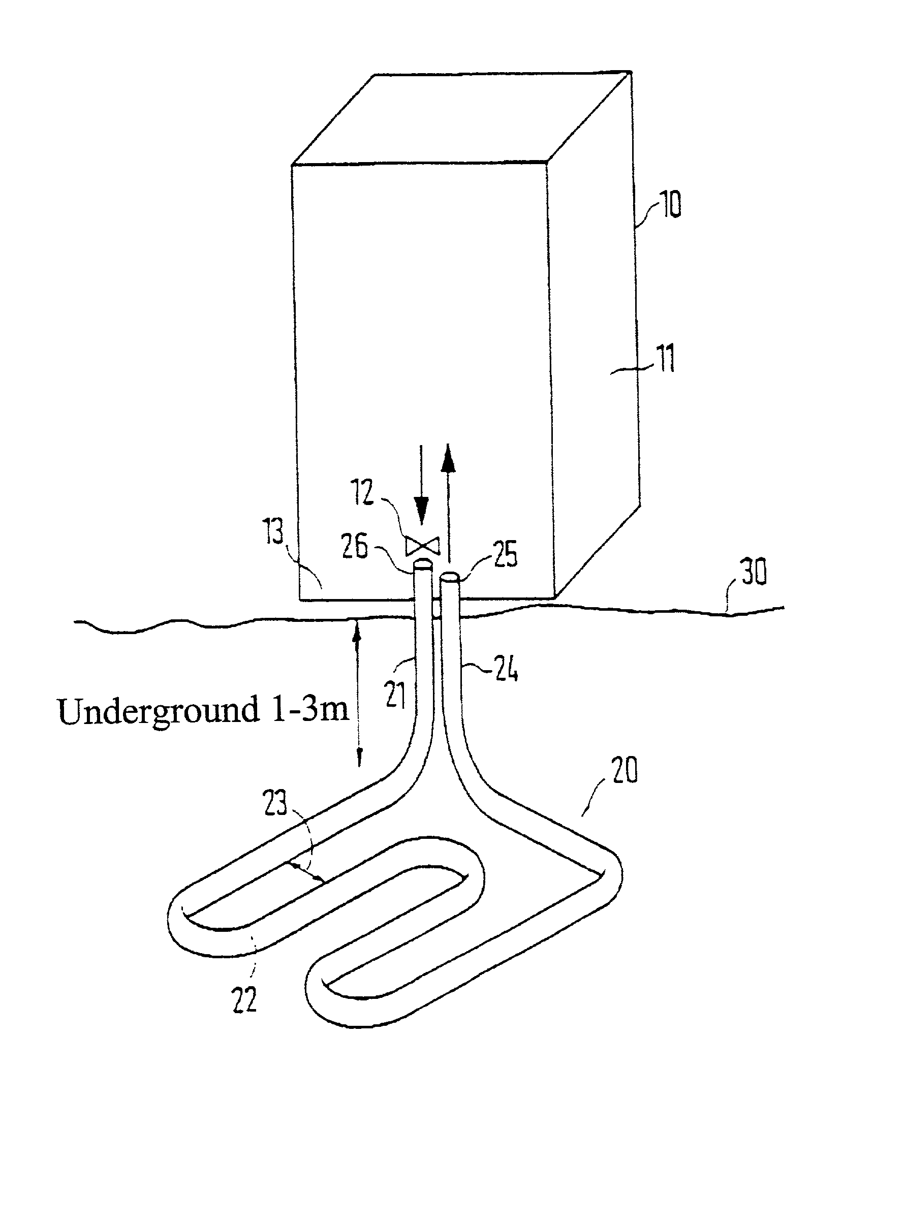
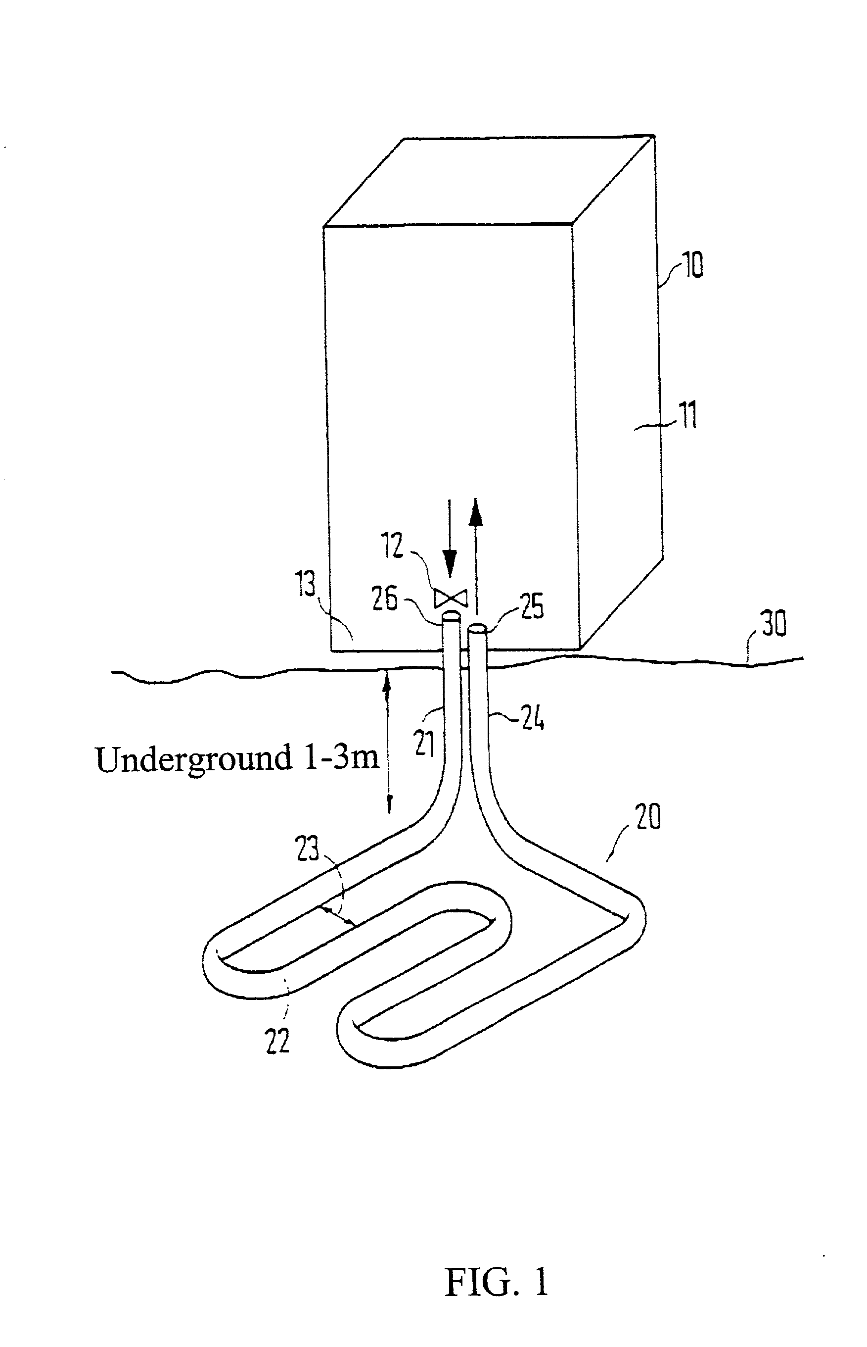
[0021] As shown in the drawing, a switchgear cabinet 10 is placed above ground level 30. The switchgear cabinet 10 has a switchgear cabinet base 13 which is fixed in place on a concrete seal set in the ground. The outlet line 21 and the inlet line 24 of an underground heat exchanger 20 project out of the concrete seal. The outlet line 21 forms the aspirating opening 26, and the inlet line 24 forms the exhaust opening 25. A fan 12 is assigned to the aspirating opening 26. The fan 12 has a direct current motor, which is operated by a battery maintained in the interior 11 of the switchgear cabinet. As shown in the drawing, the fan 12 is also arranged in the interior of the switchgear cabinet. Thus it does not transmit any, or only negligible, noise emissions to the outside. The underground heat exchanger 20 is embodied as a flexible plastic pipe, which is placed into the ground in a meander shape. In the present case, the depth of placement is selected to be between one and three meter...


PUM


Abstract

A switchgear cabinet with an air-conditioning device having a heat exchanger, wherein the air in the interior of the switchgear cabinet can be or is conducted to the heat exchanger and can be conditioned by the heat exchanger. Effective air-conditioning of the interior of the switchgear cabinet, along with simultaneously reduced energy requirements, is possible if the heat exchanger is embodied as an underground heat exchanger and is placed into the ground.

Description

[0001] 1. Field of the Invention[0002] This invention relates to a switchgear cabinet with an air-conditioning device having a heat exchanger, wherein air in the interior of the switchgear cabinet can be or is conducted to the heat exchanger and can be conditioned by the heat exchanger.[0003] 2. Description of Related Art[0004] Switchgear cabinets of this type are known in many variations. Separate air-conditioners are installed on an outside of the switchgear cabinet for air-conditioning the interior of the switchgear cabinet are shown, for example, in German Patent Reference DE 197 12 474 C1 or German Patent Reference DE 196 09 794 C1. Air-conditioners which can mounted on the top are known from German Patent Reference DE 41 07 229 C2.[0005] Customarily, the known air-conditioners have a coolant circuit, so that sufficient amounts of waste heat can be removed from the interior of the switchgear cabinet. Air-conditioners of this type have a relatively large energy consumption. If s...

Claims


Application Information

Patent Timeline
Patent Type & Authority Applications(United States)
IPC IPC(8): H02B1/56H05K7/20
CPCH02B1/565H05K7/2059
Inventor HOLIGHAUS, HEIKONICOLAI, WALTER
Owner RITTALWERK RUDOLF LOH GMBH & CO KG
Why Eureka
Try Eureka