Optical waveguides and method of fabrication thereof

a technology of optical waveguides and fabrication methods, applied in the direction of optical waveguide light guides, instruments, optical fibres with polarisation, etc., can solve the problems of polarization dispersion of signals, industry has gone a long way, and significant expens

Inactive Publication Date: 2002-07-11
NITTO DENKO CORP
View PDF12 Cites 13 Cited by
  • Summary
  • Abstract
  • Description
  • Claims
  • Application Information

AI Technical Summary

Problems solved by technology

Industry has gone a long way at substantial expense in its efforts to create selective fibers with a certain configuration of birefringence in the fiber core.
However, it creates another problem, namely polarization dispersion of the signal.

Method used


Image

  • Optical waveguides and method of fabrication thereof
  • Optical waveguides and method of fabrication thereof
  • Optical waveguides and method of fabrication thereof

Examples


Embodiment Construction

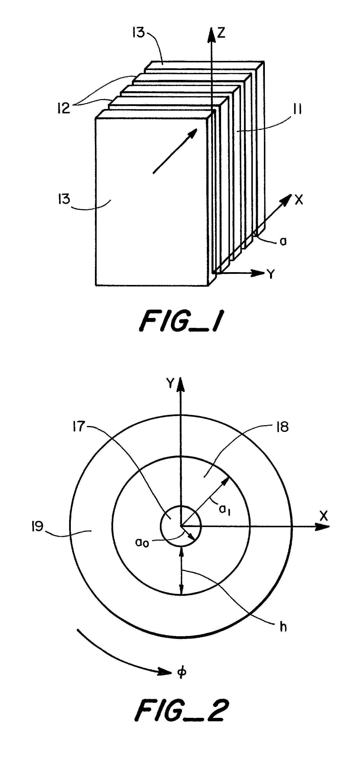
[0024] The present invention is directed to new polarization-maintaining and polarizing optical waveguides that are, for example, flat planar guides or cylindrical guides or fibers. Also described is a method of manufacturing mode-selective optical guides such as planar multilayer waveguides or cylindrical guides or fibers. The design of the waveguides has a major distinction: one of the layers is made from a highly anisotropic crystalline material coating with refraction indices that are different in different directions. By the deposition technique employed we can control the direction of the crystallographic axis of the crystals in the final film. Optical properties of crystalline film are different along a crystallographic axis and that is the major benefit that allows for influencing properties of optical waveguides by selecting material and direction or pattern of deposition.

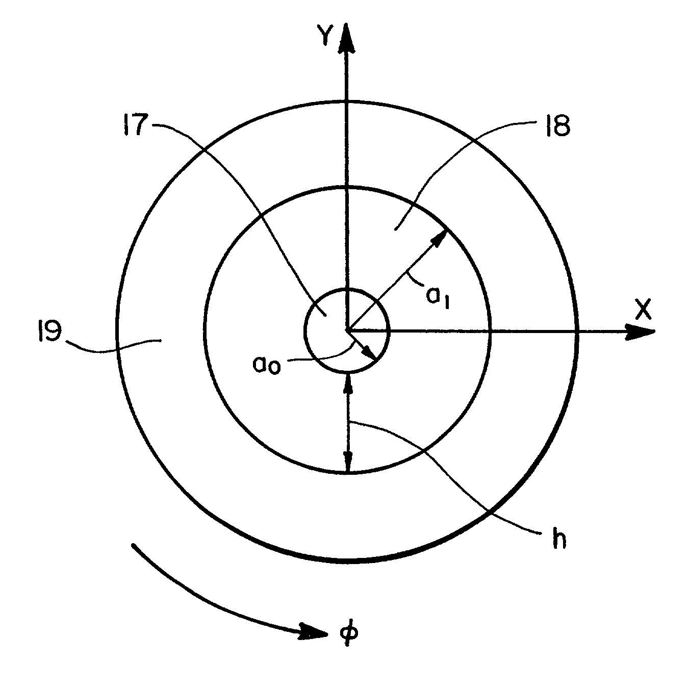
[0025] Planar guides, FIG. 1, are layers of materials that transmit light. The transmitting layer 11 is...


PUM


Abstract

Optical waveguides of the type which include a light-transmitting core and a cladding layer in said core. The optical waveguide can be planar or cylindrical such as an optical fiber. The optical waveguide is provided with an additional coating of highly biaxial or uniaxial crystalline material with different refraction indices in different directions.

Description

[0001] This application claims priority to U.S. Provisional Application Serial No. 60 / 249,034 filed Nov. 14, 2000.[0002] The present invention relates to components for use in optical systems such as optical waveguides for communication devices and to components that control light propagation through optical guides and provides selectivity in regard to spatial and directional distribution of electromagnetic field of light in the guide cross-section.BACKGROUND OF INVENTION[0003] Light has several basic properties such as brightness, wavelength (or color), and polarization. In optical devices we would like to control all of them and by modulation of these properties to signal something meaningful to a recipient on another end of a waveguide.[0004] Polarization maintenance (or mode selectivity) is an important feature in light transmitting devices because of requirements imposed by coherent detection systems like homodynes and heterodynes (J. M. Senior, Optics Fiber Communications, N.Y...

Claims


Application Information

Patent Timeline
Patent Type & Authority Applications(United States)
IPC IPC(8): G02B6/126G02B6/02G02B6/024G02B6/036G02B6/13
CPCG02B6/02385G02B6/024G02B6/03622G02B6/03694
Inventor LAZAREV, PAVEL I.PAUKSHTO, MICHAEL V.
Owner NITTO DENKO CORP
Why Eureka
Try Eureka