Thrust enhancing propeller guard assembly

Inactive Publication Date: 2002-07-18
MORRELL GREGORY C
View PDF0 Cites 7 Cited by
  • Summary
  • Abstract
  • Description
  • Claims
  • Application Information

AI Technical Summary

Problems solved by technology

Unguarded rotating propellers present a substantial hazard to submerge

Method used


Image

  • Thrust enhancing propeller guard assembly
  • Thrust enhancing propeller guard assembly
  • Thrust enhancing propeller guard assembly

Examples


Embodiment Construction

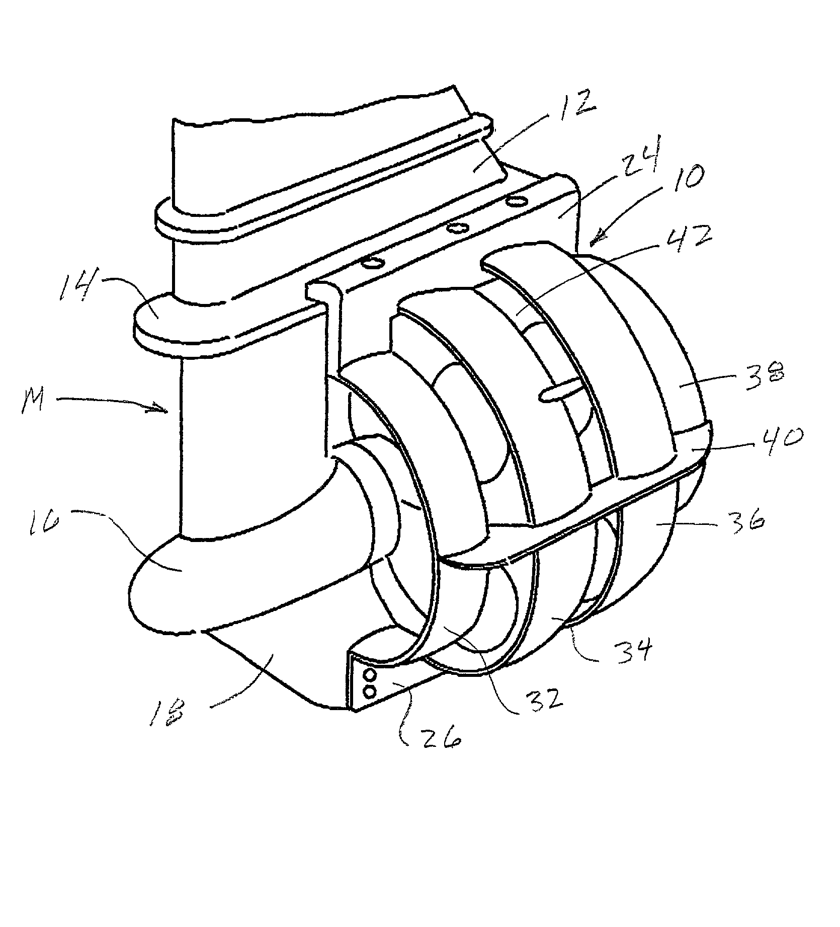
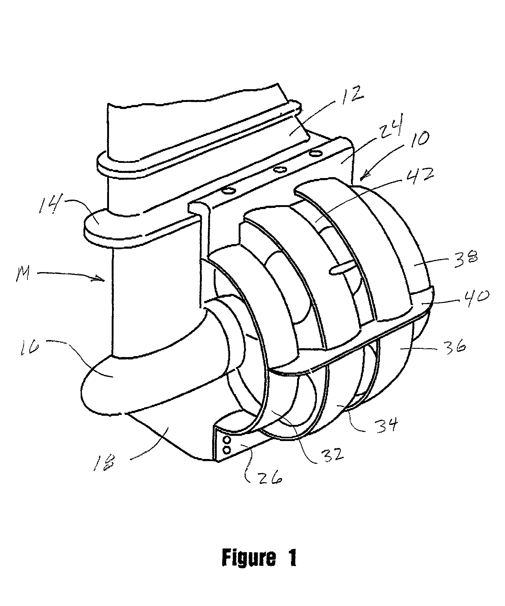
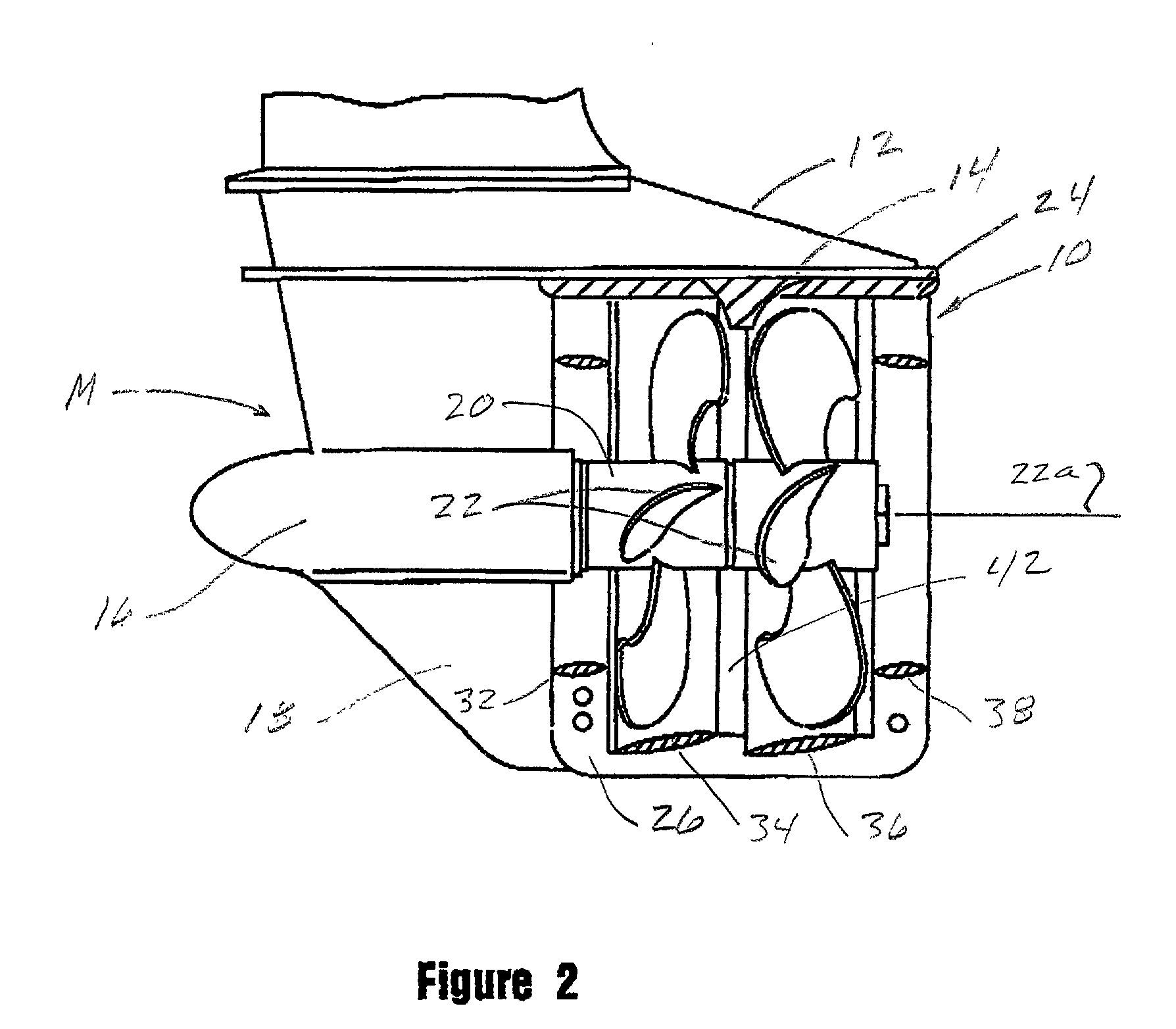
[0016] Referring to the drawings and particularly to FIGS. 1, 2 and 3, one form of the propeller guard assembly of the invention is there shown and generally designated by the numeral 10. Assembly 10 is shown in the drawings affixed to a conventional, commercially available outboard motor "M". Motor "M" includes a housing 12 having a cavitation plate 14, a generally torpedo shaped central portion 16 and a skeg 18 connected to and extending downwardly from portion 16. A propeller shaft 20 extends from central portion 16 and carries a pair of contra rotating propellers 22 that rotate about the longitudinal axis 22a of shaft 20 (FIG. 2).

[0017] Connected to cavitation plate 14 is a pair of first, oppositely disposed mounting members 24, the purpose of which will presently be described (FIGS. 1 and 3). Similarly, a pair of second, oppositely disposed mounting members of 26 are mounted on skeg 22. Attached to mounting members 24 and 26 is the novel propeller guard assembly of the inventio...


PUM


Abstract

A propeller guard assembly for water craft that, in cooperation with a rotating propeller, creates a substantial increase in propulsive thrust and provides improved all around shielding of the latest state of the art propeller configurations. The increase in propulsive thrust of the propeller guard assembly of the invention is created primarily by the angle of the attack and hydrofoil cross section of the four guard rings or cowlings of the device. A secondary reason for the increase in propulsive thrust of the propeller guard assembly of the invention resides in the fact that the thrust realized is equal to the ratio between the effective projected propeller area and the area of trailing edges of the large primary and secondary guard rings which decreases the tendency of the propeller race to spread, particularly at high propeller slip during acceleration and take off.

Description

[0001] 1. Field of the Invention[0002] The present invention relates generally to fluid propulsion systems. More particularly, the invention concerns a novel thrust enhancing propeller guard assembly for use in connection with outboard motors.[0003] 2. Discussion of the Prior Art[0004] Rotating propellers are an integral aspect of outboard motors of the character used to propel various types of small watercraft. Unguarded rotating propellers present a substantial hazard to submerged objects and to people in the water being traversed by the watercraft. Therefore, there is a need for propeller guard that not only guards against damage caused by the rotating propellers of an outboard motor, but also preferably enhances the propulsion characteristics of the motor. As will be better understood from the description that follows, the novel propeller guard assembly of the present invention accomplishes both of these desired results. Additionally the unique propeller guard assembly of the pr...

Claims


Application Information

Patent Timeline
IPC IPC(8): B63H5/10B63H5/14B63H5/16B63H20/00
CPCB63H5/10B63H5/14B63H5/165B63H20/00
Inventor SCHULTZ, WILLIAM C.MORRELL, GREGORY C.
Owner MORRELL GREGORY C
Why Eureka
Try Eureka