Transposed winding for random-wound electrical machines operating at high frequencies

a technology of random-wound electrical machines and transposed windings, which is applied in the direction of windings, dynamo-electric components, mechanical energy handling, etc., can solve the problems of increasing the resistance (i.e. power loss) of the motor, and amplifying the effect of increased power loss

Inactive Publication Date: 2002-07-25
CAPSTONE TURBINE
View PDF14 Cites 66 Cited by
  • Summary
  • Abstract
  • Description
  • Claims
  • Application Information

AI Technical Summary

Benefits of technology

[0050] Various other objects, features and attendant advantages of the present invention will be more fully appreciated as the same becomes better understood from the following detailed description when considered in connection with the accompanying drawings in which like reference characters designate like or corresponding parts throughout the several views.

Problems solved by technology

As a result, the effective number of current-carrying wires available to carry current is smaller than the actual number of current-carrying wires, thus also increasing the resistance (i.e. power loss) in the motor.
Since the current migration effect increases with frequency, increased power losses are amplified as the frequency of the motor increases.

Method used


Image

  • Transposed winding for random-wound electrical machines operating at high frequencies
  • Transposed winding for random-wound electrical machines operating at high frequencies
  • Transposed winding for random-wound electrical machines operating at high frequencies

Examples


Embodiment Construction

[0050] Various other objects, features and attendant advantages of the present invention will be more fully appreciated as the same becomes better understood from the following detailed description when considered in connection with the accompanying drawings in which like reference characters designate like or corresponding parts throughout the several views.

[0051] Mechanical Structural Embodiment of a Turbogenerator

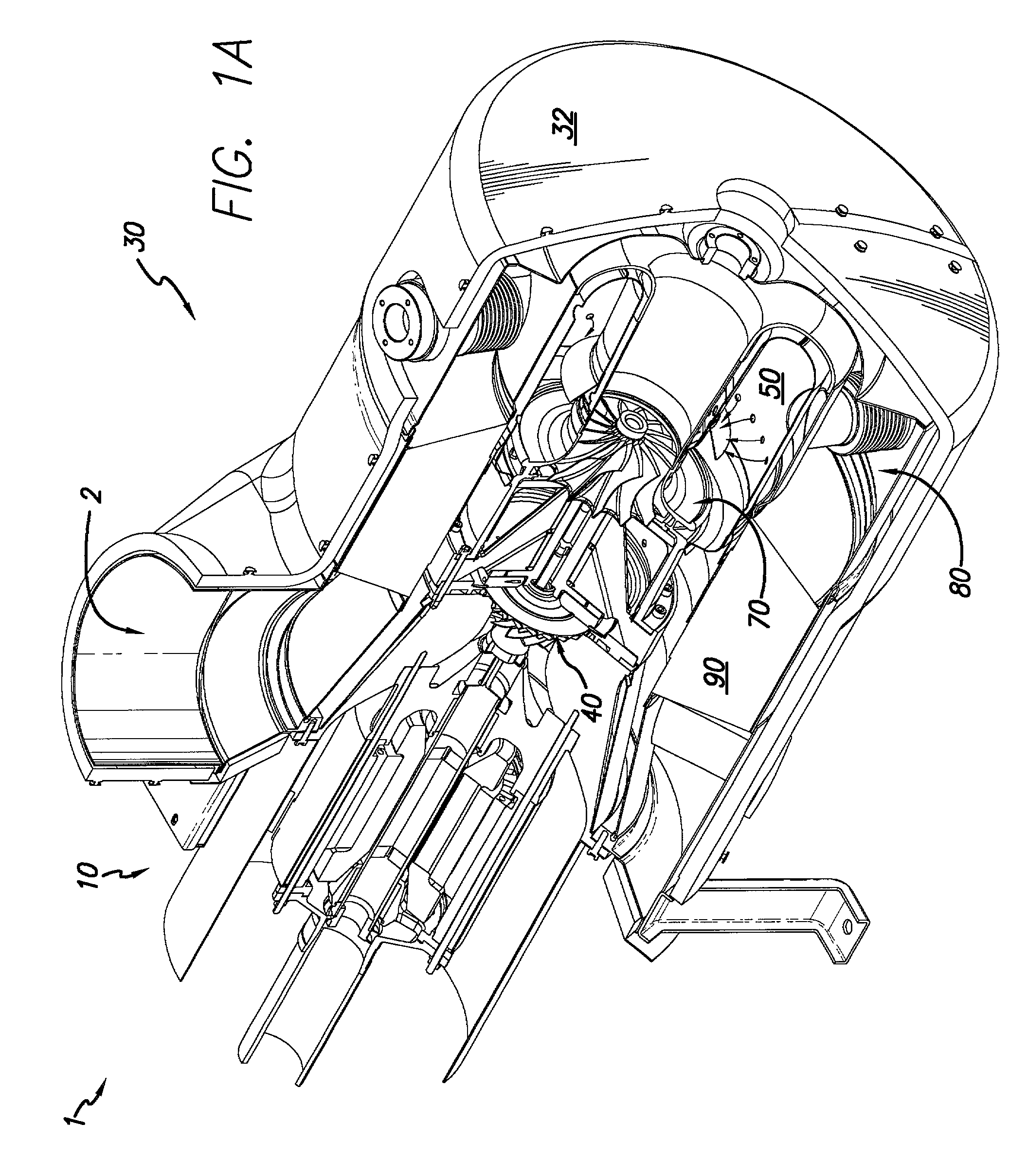
[0052] With reference to FIG. 1A, an integrated turbogenerator 1 according to the present invention generally includes motor / generator section 10 and compressor-combustor section 30. Compressor-combustor section 30 includes exterior can 32, compressor 40, combustor 50 and turbine 70. A recuperator 90 may be optionally included.

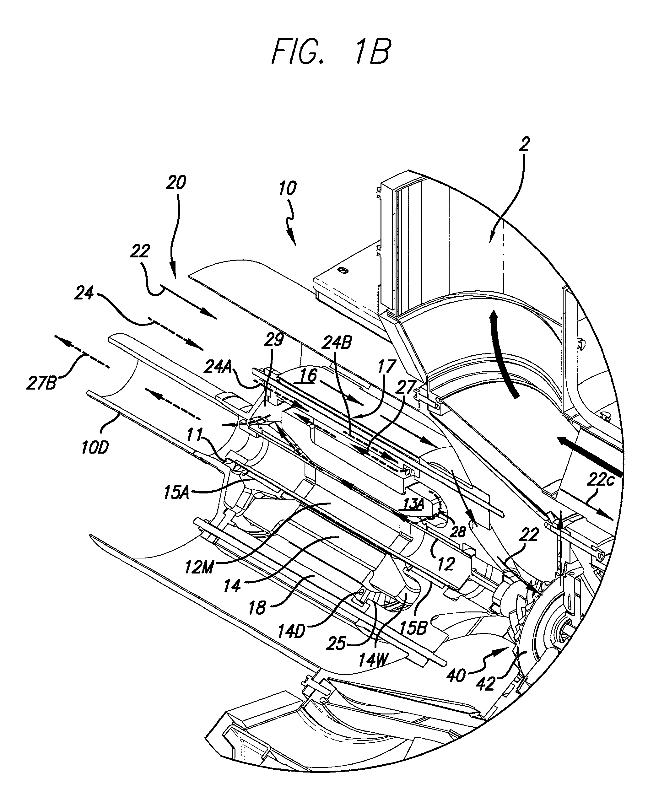
[0053] Referring now to FIG. 1B and FIG. 1C, in a currently preferred embodiment of the present invention, motor / generator section 10 may be a permanent magnet motor generator having a permanent magnet rotor or sleeve 12. Any other suitable type of...


PUM


Abstract

A random-wound winding for an electrical machine including interconnected wire layers, wherein the interconnected wire layers include randomly wound wires and are configured upon placement in the electrical machine to have substantially the same impedance. Accordingly, the random wound windings can include a first coil having layers of wires randomly wound on the first coil with the layers configured in a first layering order, a second coil having layers of wires randomly wound on the second coil with the layers configured in a second layering order transposed relative to the first layering order, and at least one electrical interconnection configured to serially connect the layers of the first coil to the layers of the second coil such that an average axial position of all interconnected layers is substantially the same. The random wound windings can include a coil having layers of wires randomly wound on the coil with one side of the coil having the layers configured in a first layering order and an opposing side of the coil having the layers configured in a second layering order transposed relative to the first layering order, wherein an average axial position of the layers substantially the same.

Description

[0001] This patent application claims benefit of and priority to U.S. provisional application Ser. No. 60 / 245,704 filed Nov. 2, 2000, and the entire contents of the provisional application are incorporated herein by reference.[0002] 1. Field of the Invention[0003] This invention relates to the general field of high-frequency electrical machines, and more particularly to an improved system and method to reduce the current migration effect acting on windings in electrical machines.[0004] 2. Discussion of the Related Art[0005] As used herein, a wire means a long strand of conductive material. An electrically insulating sheath or coating can surround the conductor surface of the strand. On wires, the skin effect constrains high frequency (HF) electric current carried by the wires to flow in an outer cross-sectional area of the conductive cross-section of each wire. Fine-gauge wires, whose thickness is generally less than two skin depths, are used to carry HF current. Wires having a cumu...

Claims


Application Information

Patent Timeline
Patent Type & Authority Applications(United States)
IPC IPC(8): H02K3/14H02K3/28H02K7/18H02K15/04H02K15/06
CPCH02K3/14H02K3/28H02K7/1823H02K15/04H02K15/06
Inventor QIN, DINYUSWINTON, MICHAELSWINTON, JAN
Owner CAPSTONE TURBINE
Why Eureka
Try Eureka