Electrically operated parking brake apparatus

a technology of parking brakes and electric motors, which is applied in the direction of braking systems, transportation and packaging, gearing, etc., can solve the problems of inability to estimate the magnitude of the brake operating force from the magnitude of the load of the motor, and the release of the brake force applied to the wheel brakes,

Inactive Publication Date: 2002-08-01
HONDA MOTOR CO LTD
View PDF5 Cites 35 Cited by
  • Summary
  • Abstract
  • Description
  • Claims
  • Application Information

AI Technical Summary

Problems solved by technology

This leads to the possibility that the brake force applied to the wheel brakes may be released.
However, while the worm reduction gear has the function to prevent the reverse rotation of the screw-threaded shaft, since the worm reduction gear is not constructed to transmit the load (i.e., the tension of the cables) from the screw mechanism to the electric motor side in a reverse fas

Method used


Image

  • Electrically operated parking brake apparatus
  • Electrically operated parking brake apparatus
  • Electrically operated parking brake apparatus

Examples


Embodiment Construction

[0027] A mode for carrying out the invention will be described below based on an embodiment of the invention illustrated in FIGS. 1 to 10.

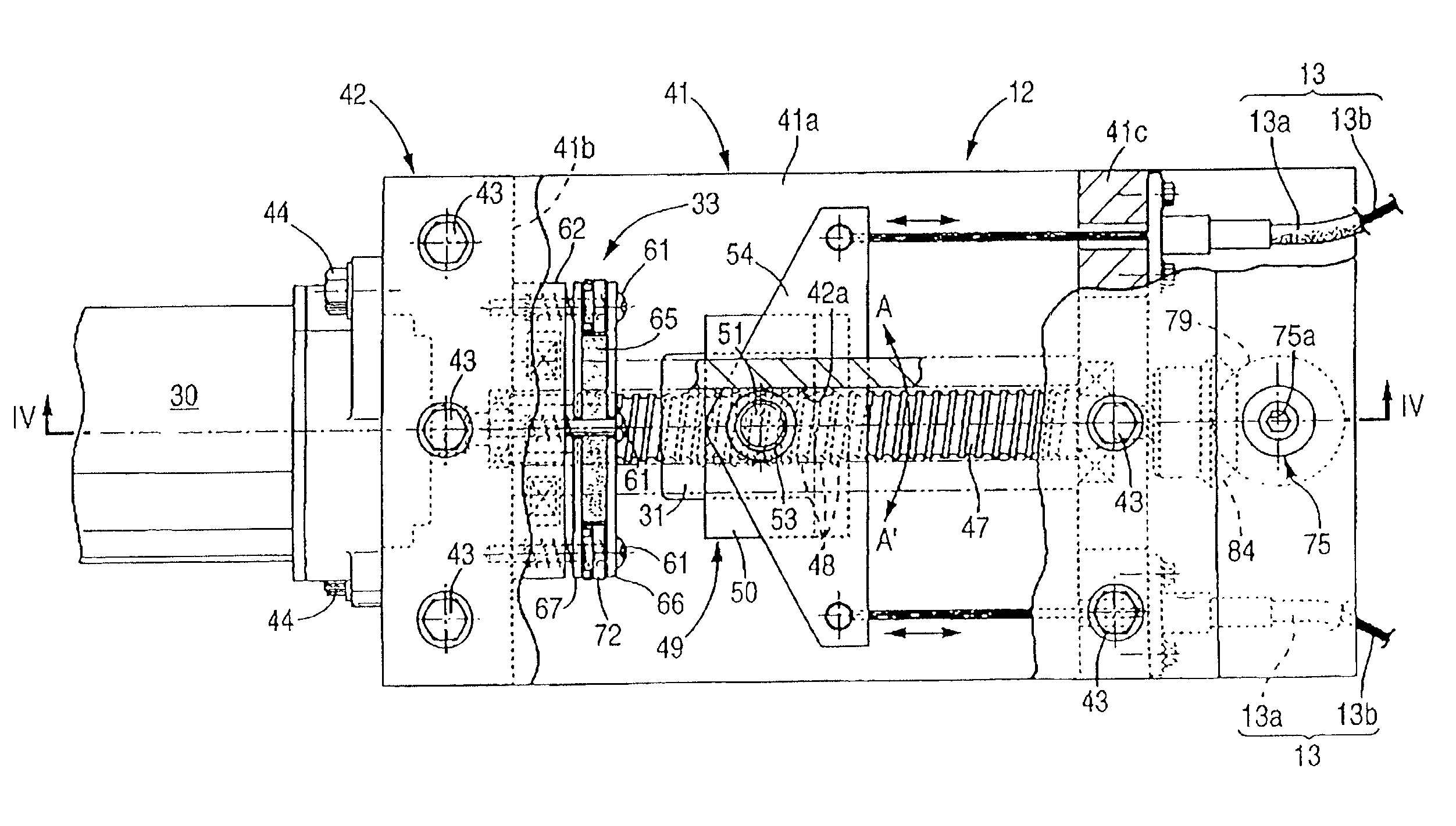
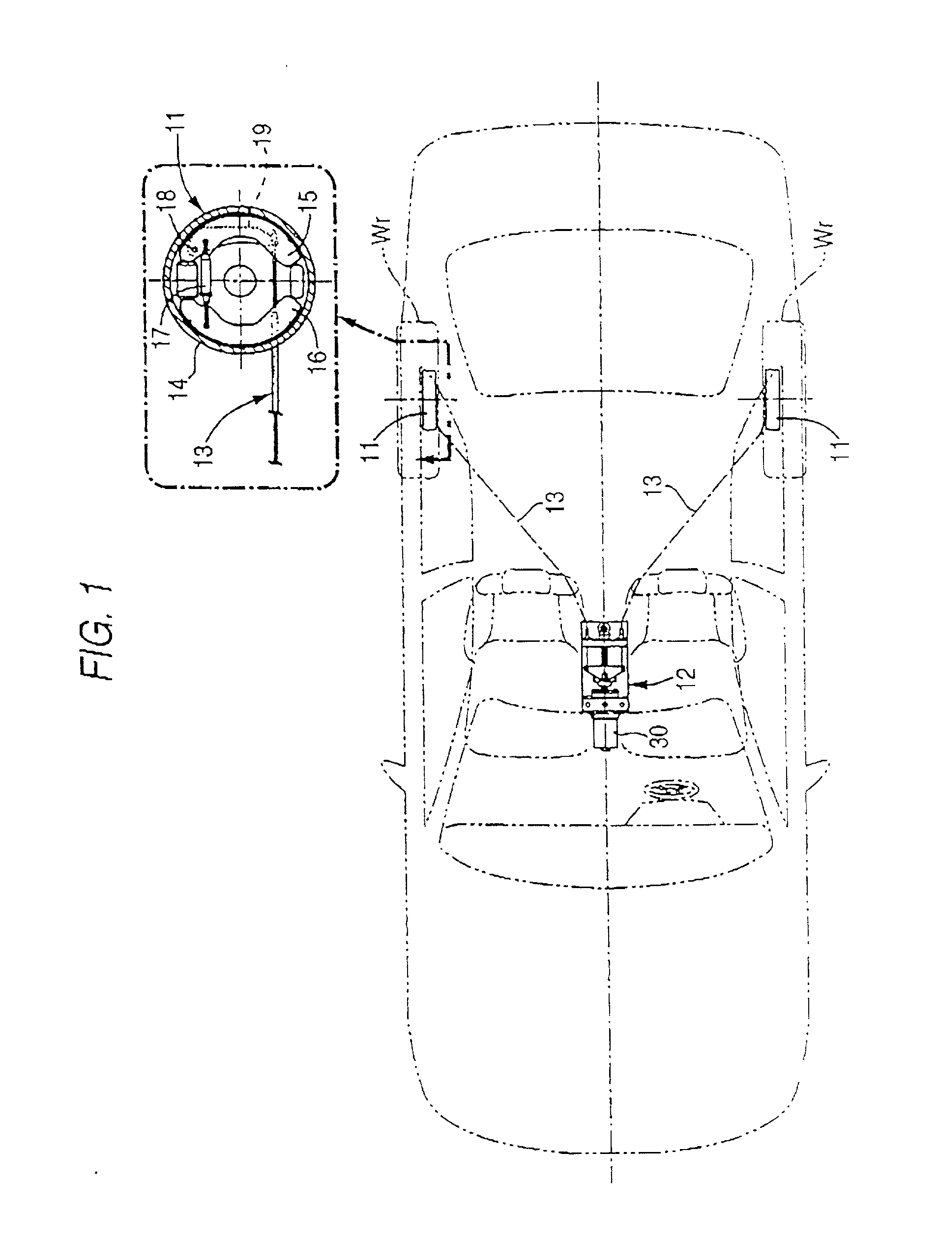
[0028] As shown in FIG. 1, drum type wheel brakes 11, 11 are provided on left and right rear wheels Wr, Wr of a vehicle, and an electrically operated brake apparatus 12 disposed beside a driver's seat is connected to the wheel brakes 11, 11 via left and right Bowden cables 13, 13. Each wheel brake 11 includes a brake drum 14, a pair of brake shoes 15, 16, a connecting rod 17 and a lever 19. The brake shoes 15, 16 are adapted to be brought into contact with an inner circumferential surface of the brake drum 14. The connecting rod 17 is adapted to connect the pair of brake shoes 15, 16. The lever 19 is rotatably supported at one end thereof on the brake shoe 15 via a pin 18, and the Bowden cable 13 is connected to the other end thereof.

[0029] Consequently, when the Bowden cable 13 is pulled with an electric motor 30 provided on the electrically oper...


PUM


Abstract

An electrically operated parking brake apparatus that includes an electric motor and a screw mechanism The screw mechanism includes a screw-threaded shaft adapted to be rotationally driven by the electric motor, and a nut member meshing with the screw-threaded shaft, the nut member being movable along the screw-threaded shaft by the rotation of the screw-threaded shaft. The parking brake apparatus also includes a transmission member connected to the nut member for transmitting a brake operating force to a wheel brake, and a rotation preventing unit for preventing the rotation of the screw-threaded shaft so as to hold the brake operating force by fixing the position of the nut member relative to the screw-threaded shaft. The rotation preventing unit in one embodiment is an electromagnetic brake for confining the screw-threaded shaft to a stationary portion of a vehicle body.

Description

[0001] 1. Field of the Invention[0002] The present invention relates to a parking brake apparatus for applying a brake force to wheels of a parked vehicle. More particularly, the present invention is related to an electrically operated parking brake apparatus for applying the brake force to the wheels through the driving force of an electric motor without relying upon the force applied by the hand or foot of a driver.[0003] 2. Description of the Related Art[0004] JP-A-2000-309255 discloses an electrically operated parking brake apparatus with a screw mechanism having in turn a screw-threaded shaft adapted to be rotationally driven by an electric motor, and a nut member adapted to mesh with the screw-threadedshaft. When the screw-threadedshaft is rotated, the nut member is moved along the screw-threaded shaft, whereby a brake operating force is transmitted to wheel brakes via cables connected to the nut member.[0005] Since the electrically operated parking brake apparatus disclosed i...

Claims


Application Information

Patent Timeline
IPC IPC(8): B60T13/02B60T13/74F16D65/18F16D65/28F16H25/20
CPCB60T13/02B60T13/746
Inventor MIYAKAWA, JUNTANIGUCHI, MAKOTOYAMANAKA, FUMIKAGEIWAGAWA, YOSHIHIROKIN, KEIYUKICHIMA, YUTAKA
Owner HONDA MOTOR CO LTD
Why Eureka
Try Eureka