Drawer slide socket and method

a technology for sliding sockets and drawers, applied in drawers, furniture parts, domestic applications, etc., can solve problems such as difficulty in leveling or horizontal installation of other self-adjusting brackets, subsequent operation problems during drawer use,

Inactive Publication Date: 2002-08-01
HUGHES SUPPLY & MFG
View PDF0 Cites 15 Cited by
  • Summary
  • Abstract
  • Description
  • Claims
  • Application Information

AI Technical Summary

Benefits of technology

[0005] Thus, with the problems and disadvantages of prior art drawer slide brackets or sockets which are self-adjusting, the present invention was conceived and of its objectives is to provide a drawer slide socket which is relatively inexpensive to manufacture and easy to install by relatively inexperienced persons.
[0009] It is yet a further objective of the present invention to provide a method of installing a drawer slide utilizing the slide socket as aforedescribed for quick and efficient assembly and installation.
[0011] The aforesaid and other objectives are realized by providing a drawer slide socket having a base integrally formed from a polymeric material and which includes a pair of mounting legs projecting therefrom. A cap on each leg overhangs the same to provide a catch for the slide socket and prevents it from detaching from the rear cabinet wall. Slidably affixed to the base is a receptor for containing the end of a drawer slide as conventionally used in the cabinet industry. The base also defines a flexible stop member which limits the lateral movement of the receptor.
[0012] The method of installation includes positioning the slide socket on the drawer section of a cabinet slide and thereafter placing the slide socket on the inside rear cabinet wall in preformed apertures. Next, the cabinet section of the drawer slide is attached to a drawer section of the slide for cooperative engagement therewith. The receptor allows for lateral, self-adjusting movement of the drawer to ensure free, easy movement thereof as the drawer is opened and closed during normal use.

Problems solved by technology

Problems have arisen with standard self-adjusting brackets which affix to the rear cabinet wall and permit a lateral movement of the drawer.
Since certain of the prior cabinet wall brackets are formed of metal they can be deformed during shipping or installation, causing subsequent operational problems during drawer use.
Other self-adjusting brackets are difficult to install in a level or horizontal manner to prevent "binding" of the drawer slides.
Other prior art devices are not molded or manufactured to the close tolerances required for precise, even movement during installation and continual drawer usage.
Other prior art drawer slide brackets require skill and expertise in mounting for proper functioning and are difficult to align.

Method used


Image

  • Drawer slide socket and method
  • Drawer slide socket and method
  • Drawer slide socket and method

Examples


Embodiment Construction

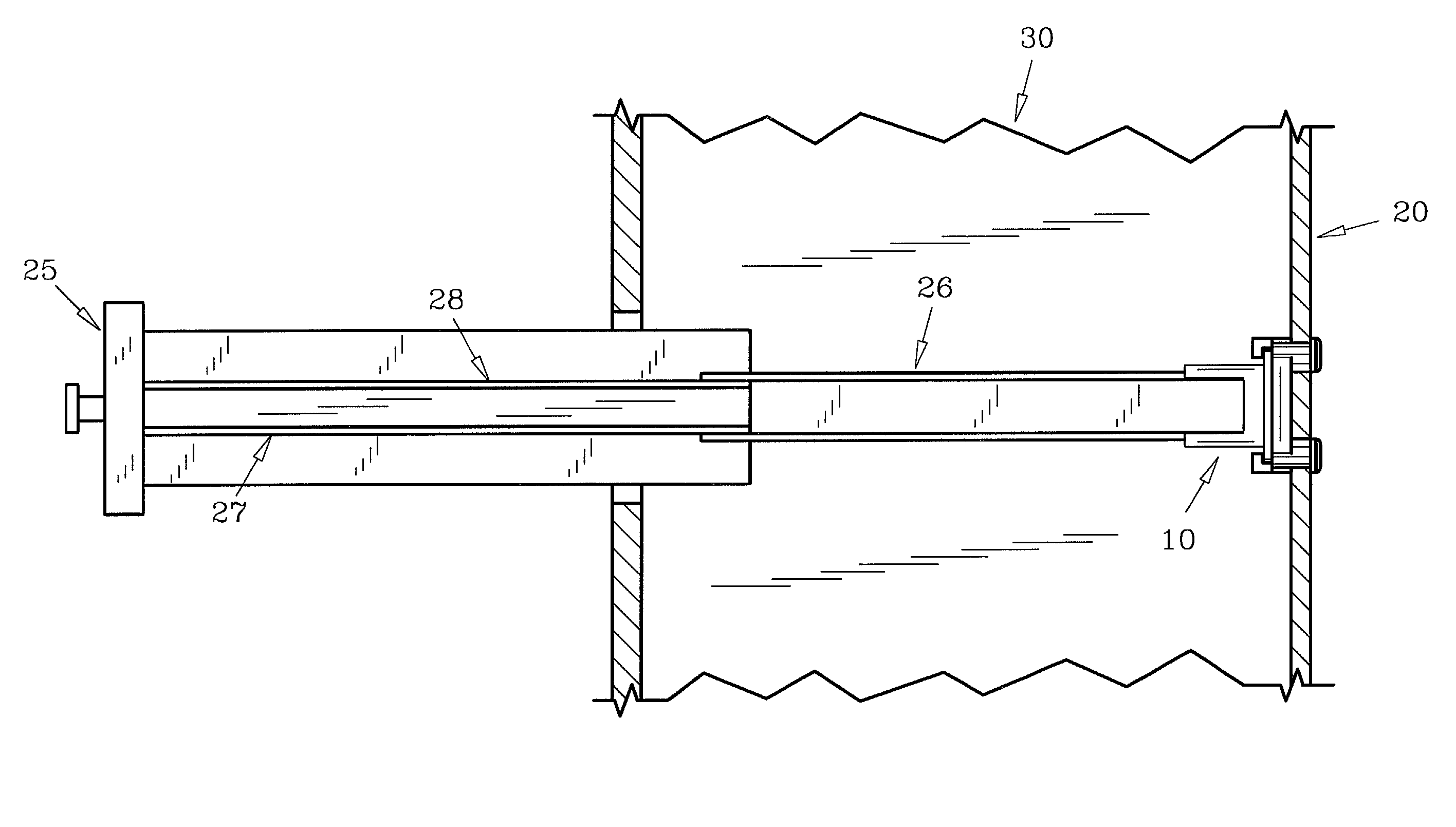
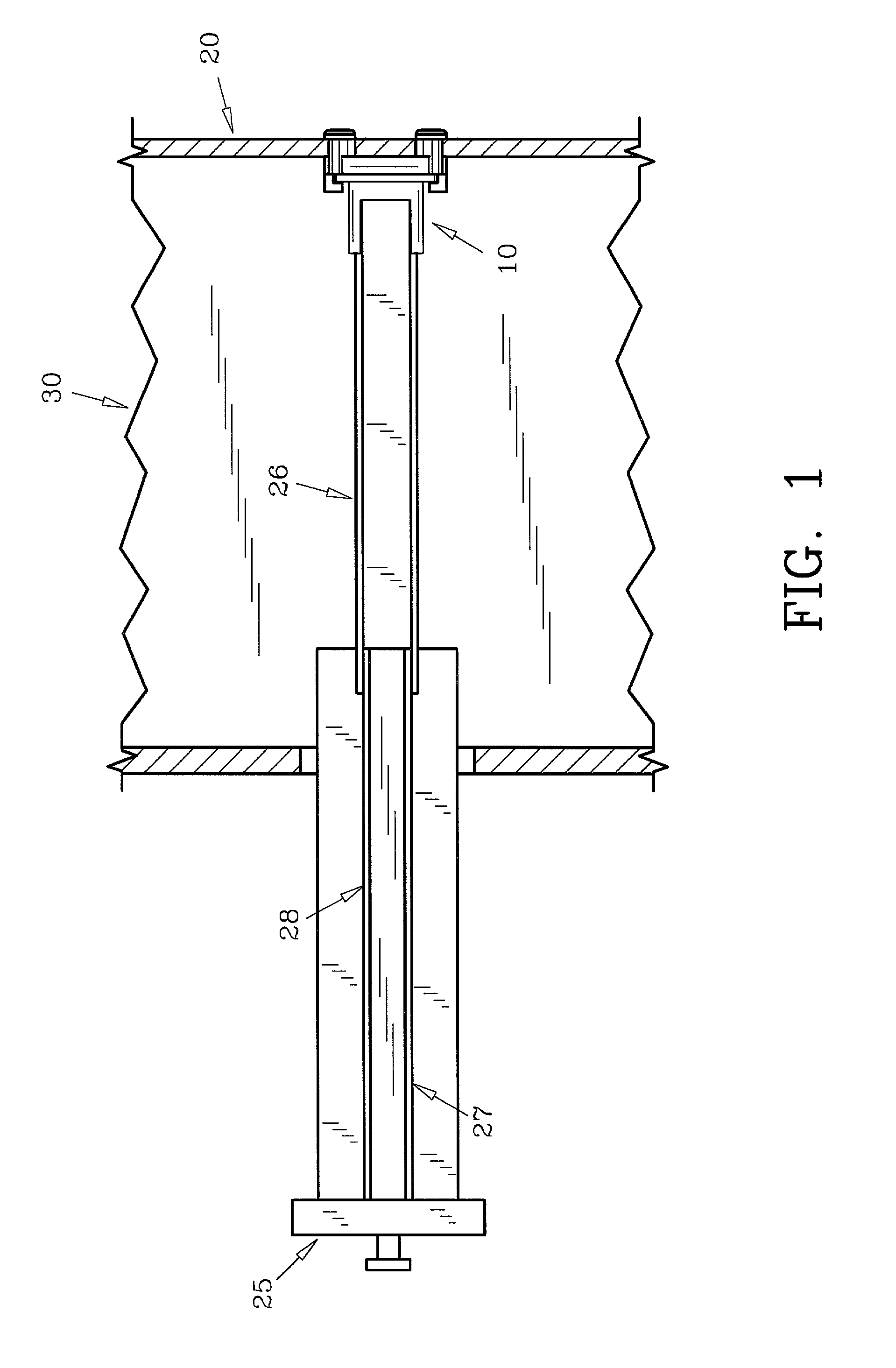
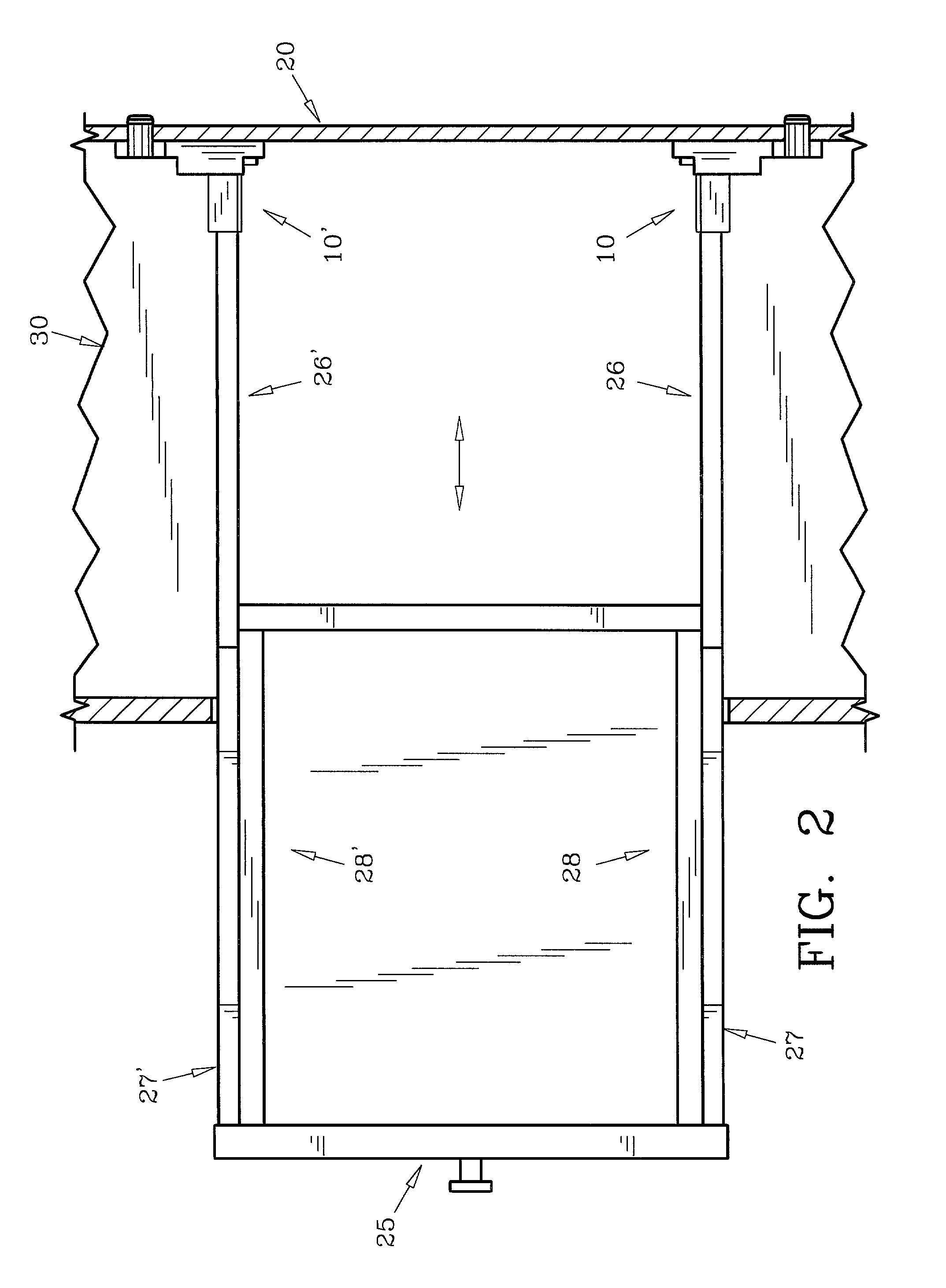
[0023] For a better understanding of the invention and it operation, turning now to the drawings, FIG. 1 shows a schematic cross-sectional view of a typical installation of preferred drawer slide socket 10 mounted on back wall 20 of cabinet 30. Cabinet 30 may be, for example, a kitchen cabinet and have one or more drawers 25 as is standard in the industry. Drawer slide socket 10 receives the terminal end of c-shaped cabinet section 26 of drawer slide 28. As would be understood, c-shaped drawer section 27 of telescopic drawer slide 28 is affixed to drawer 25 by screws or other fasteners (not shown) and is movable within cabinet section 26 as is usual in the trade. Drawer slide 28 is formed from metal and is one of a pair of side drawer slides used with drawer 25, the other drawer slide mounted on the opposite side as seen in FIG. 2. As would be understood, drawer slide socket 10 is used in pairs, but is generally described herein in singular fashion.

[0024] For a view of drawer slides...


PUM


Abstract

A cabinet drawer slide socket is provided which provides ease and convenience in installing cabinet drawers for kitchen, bathroom or other cabinets. The slide socket is easily attached to conventional cabinet slides and includes a pair of legs which are positioned in pre-drilled apertures in the rear cabinet wall. Leg caps lock the slide socket to the rear cabinet wall and includes a slide receptor which is movable laterally for self-adjustment.

Description

[0001] The invention herein pertains to cabinets as are used in kitchens, bathrooms or the like and in particular pertains to a self-adjusting slide socket for mounting side drawer slides.DESCRIPTION OF THE PRIOR ART AND OBJECTIVES OF THE INVENTION[0002] Various types of drawer guides and or slides have been used in the furniture industry for many years to permit drawers to easily open and close. Such slides are generally attached along the sides or bottom of the drawer and are formed of metal. Certain of these slides consist of c-shaped channel members which are positioned on each side of the drawer opening of the cabinet and engages a roller attached to the drawer. Other drawer slides contain two or more sections which telescope as the drawer opens and closes. Examples of such slides are shown in U.S. Pat. Nos. 3,658,399, 3,675,883, 4,176,890, 4,244,546, 4,278,309 and 4,927,216.[0003] While certain of the cabinet slide sections are affixed to the cabinet sidewalls, others extend t...

Claims


Application Information

Patent Timeline
Patent Type & Authority Applications(United States)
IPC IPC(8): A47B88/04
CPCA47B88/044A47B88/43
Inventor CROOKS, TIMOTHY K.SMITH, FARRELL
Owner HUGHES SUPPLY & MFG
Why Eureka
Try Eureka