Planar waveguide dispersion compensator

a compensator and waveguide technology, applied in the direction of optical waveguide light guide, instruments, optics, etc., can solve the problems of optical signals propagating along a fiber or within a planar waveguide being subject to delays in their propagation time, difficult to compensate, and chromatic (wavelength dependent) dispersion in digital optical transmission systems such as glass fiber pulse code modulation (pcm)

Inactive Publication Date: 2002-08-01
RPX CLEARINGHOUSE
View PDF0 Cites 14 Cited by
  • Summary
  • Abstract
  • Description
  • Claims
  • Application Information

AI Technical Summary

Problems solved by technology

Digital optical transmission systems such as glass fiber pulse code modulation (PCM) transmission systems are known to suffer from chromatic (wavelength dependent) dispersion.
Such dispersion leads to optical signals propagating along a fiber or within a planar waveguide being subject to delays in their propagation time which depend on their wavelength.
The variable delay which chromatic dispersion generates in optical communications networks creates several problems, especially in digital optical transmission systems.
A number of factors influence dispersion and delay and it is not easy to compensate in a planar waveguide device for the group velocity dispersion of the transmission system through which an optical pulse propagates.
Although polymer materials can provide a compensating dispersion of group velocity, such materials are generally considered unsuitable for pulse reforming due to size constraints in a planar waveguide device.
Conventional dispersion compensators using techniques such as stretchable chirped fibre gratings to alter the refractive index of the fibres implementing the grating are generally complex, expensive, and are subject to fatigue.

Method used


Image

  • Planar waveguide dispersion compensator
  • Planar waveguide dispersion compensator
  • Planar waveguide dispersion compensator

Examples


Embodiment Construction

[0063] There will now be described by way of example the best mode contemplated by the inventors for carrying out the invention. In the following description numerous specific details are set forth in order to provide a thorough understanding of the present invention. It will be apparent however, to one skilled in the art, that the present invention may be practiced without limitation to these specific details. In other instances, well known methods and structures have not been described in detail so as not to unnecessarily obscure the present invention.

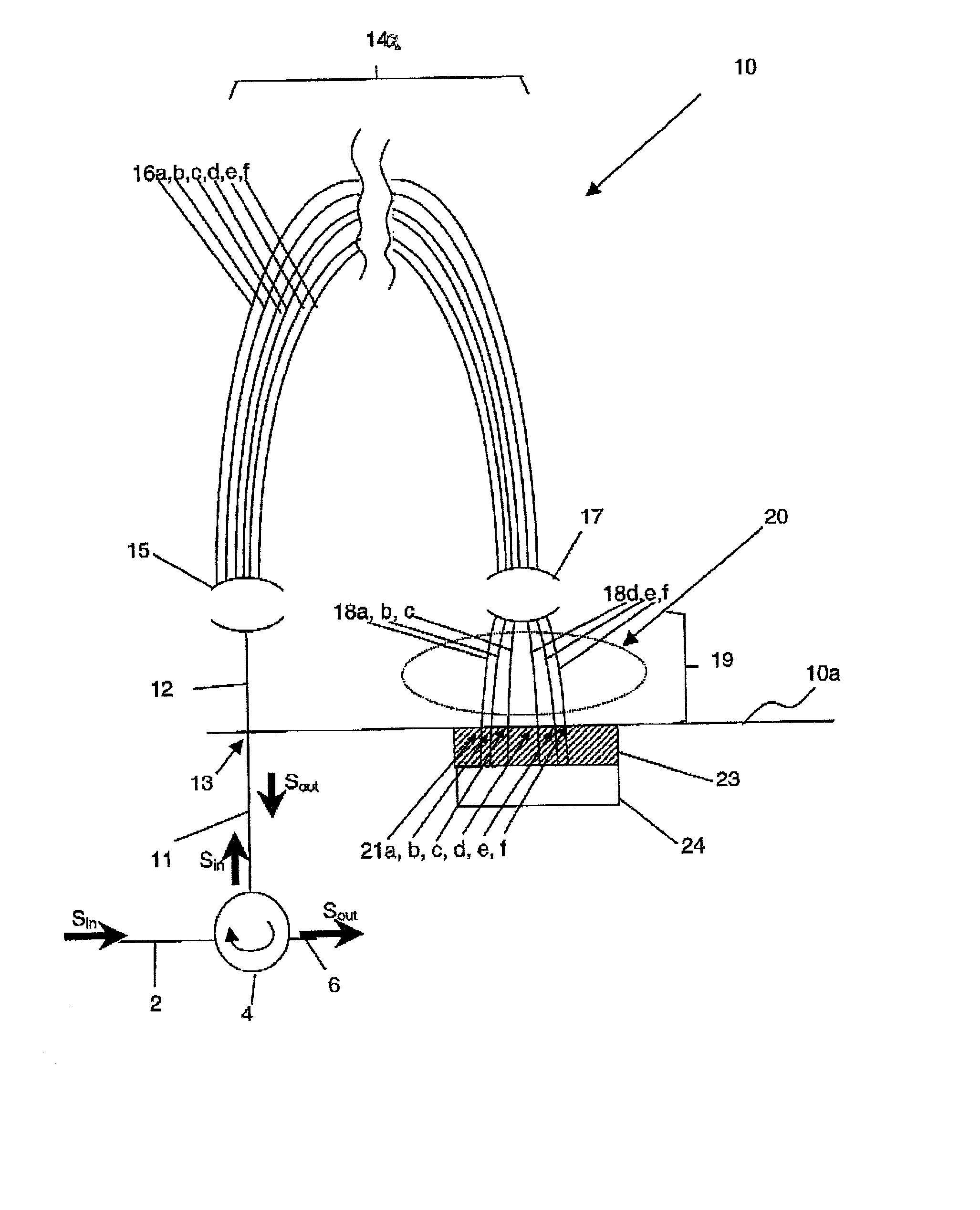
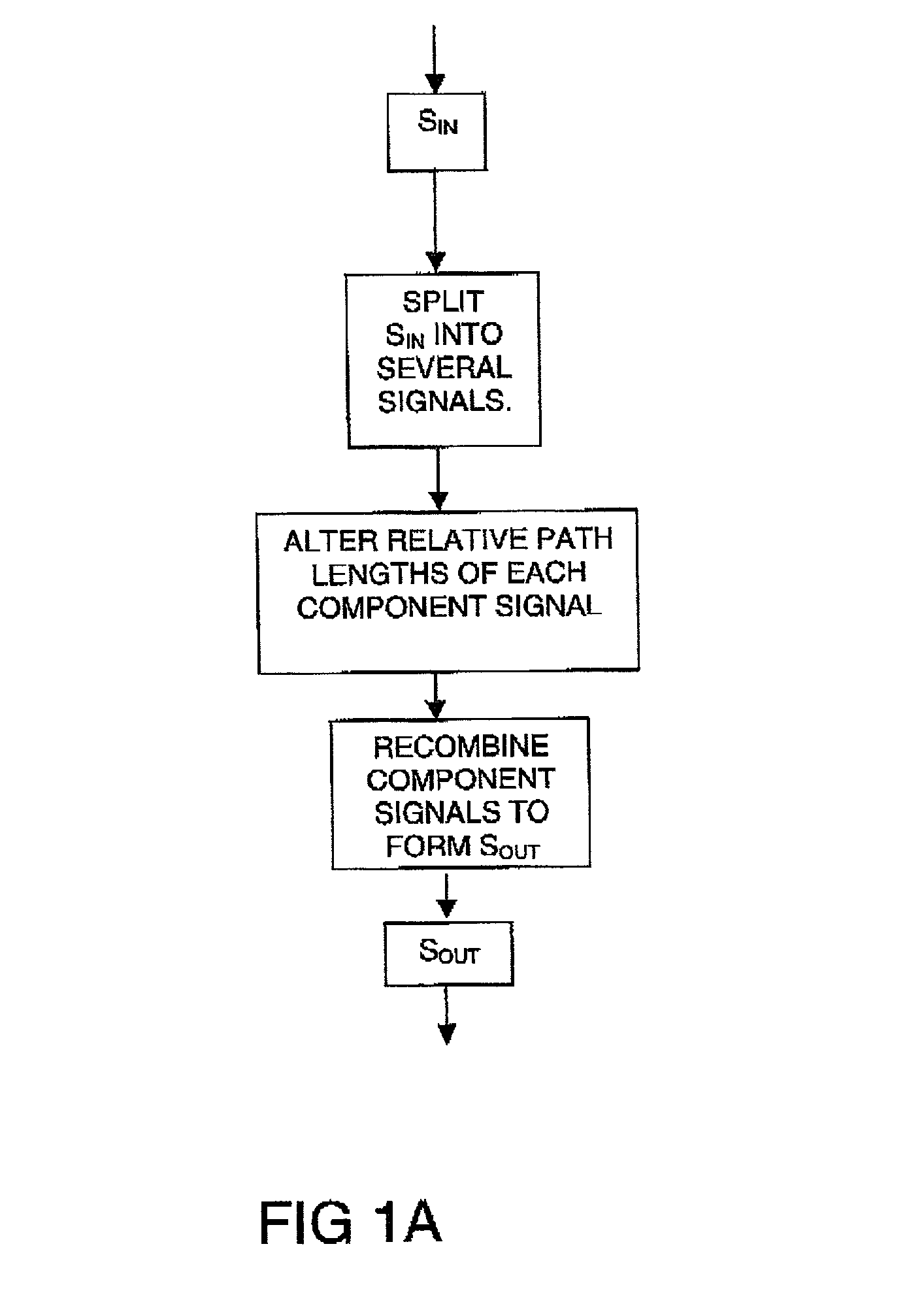
[0064] FIG. 1A illustrates a method of providing dispersion correction for an optical signal according to the invention. An optical signal S.sub.in is input into a dispersion compensator and is split into a plurality of signals enabling S.sub.in to be separated into a number of component signals S.sub.a, S.sub.b etc. The component signal S.sub.a, S.sub.b each have different wavelength passbands and follow different optical paths.

[006...


PUM


Abstract

A planar dispersion compensator for an optical signal is provided. The compensator decomposes an inputted optical signal into N component signals separated by a fractional wavelength deltalambd. Each component signal has its path-length adjusted to induce a sufficient phase shift between input and output to change the group delay of the optical signal when recombined from each of the component signals. In this manner, pulse broadening can be compensated by selectively varying the induced phase shifts to produce the desired level of opposite group delay. Portions of the substrate of the planar waveguide are removed to improve thermal responsiveness of the path-length adjustment means.

Description

RELATED APPUCATIONS[0001] This application is a Continuation-In-Part of U.S. application Ser. No. 09 / 739,528 entitled `Planar Waveguide Dispersion Compensator` from which this application claims priority.[0002] The present invention relates to a planar waveguide dispersion compensator for an optical signal, and to a method for compensating for dispersion in an optical signal. Particularly, but not exclusively, the invention further relates to a thermally responsive lens providing dispersion compensation in a planar waveguide device, and to a method of tuning a thermally responsive dispersion compensator.BACKGROUND TO THE INVENTION[0003] Digital optical transmission systems such as glass fiber pulse code modulation (PCM) transmission systems are known to suffer from chromatic (wavelength dependent) dispersion. Such dispersion leads to optical signals propagating along a fiber or within a planar waveguide being subject to delays in their propagation time which depend on their waveleng...

Claims


Application Information

Patent Timeline
Patent Type & Authority Applications(United States)
IPC IPC(8): G02B6/12G02B6/34
CPCG02B6/12011G02B6/12019G02B6/12028G02B6/29394G02B2006/12102
Inventor THOMPSON, GREORGE H. B.WHITEAWAY, JAMESBRICHENO, TERRY
Owner RPX CLEARINGHOUSE
Why Eureka
Try Eureka