
Adaptive sensitivity control, on a pixel-by-pixel basis, for a digital imager

Active Publication Date: 2002-08-08
SMAL CAMERA TECH
View PDF6 Cites 23 Cited by
  • Summary
  • Abstract
  • Description
  • Claims
  • Application Information

AI Technical Summary

Benefits of technology

[0025] A fifth aspect of the present invention is a method of adaptively controlling sensitivity, on a pixel-by-pixel basis, of a digital imager. The method selects a first illumination intensity level mapping function; determines a first transfer control function based on the selected first compression; imposes the determined first transfer control function upon a pixel of the digital imager; determines a histogram of illumination intensity levels of pixels of image data being generated by the digital imager having the determined first transfer control function imposed thereon; determines an illumination intensity level maximum, the illumination intensity level maximum representing a greatest illumination intensity level for a pixel in a sample forming the histogram; determines a second illumination intensity level mapping function, based on the determined intensity level maximum, the second illumination intensity level mapping function preventing the generation of any saturated pixels and providing a dynamic range of image data enabling each level in the histogram to be realized by the digital imager; determines a second transfer control function based on the determined second illumination intensity level mapping function; and imposes the determined second transfer control function upon a pixel of the digital imager.
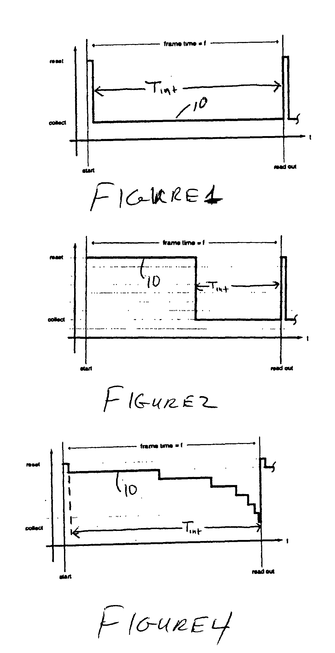
[0035] FIG. 2 shows a linear transfer control function with a decreased integration time;

Problems solved by technology

This can be problematic for imaging large dynamic range scenes, such as outdoor scenes.
There are various situations that can limit the sensitivity of a digital imager.
Since the human eye has a logarithmic response to intensity, in digital imaging, it is usually noise in the lower intensities that is of concern.
So, these properties limit the physical sensitivity of a digital imager such that a scene, having a wide range of light (illumination) intensities, cannot be imaged properly; the higher light (illumination) intensities of the scene are washed out in the imaged scene due to pixel saturation, or the low light (illumination) intensities of the scene become less resolvable due to pixel noise.
Although the physical limitations of digital imagers have been compensated for through integration time adjustment and transfer control function (resulting in the production of the control signal 10) manipulation, these conventional approaches still fail to compensate for the digital imager's physical limitations in an optimal way.
For example, the conventional processes fail to realize an illumination intensity level of the imaged scene range in which no saturated pixels exist.
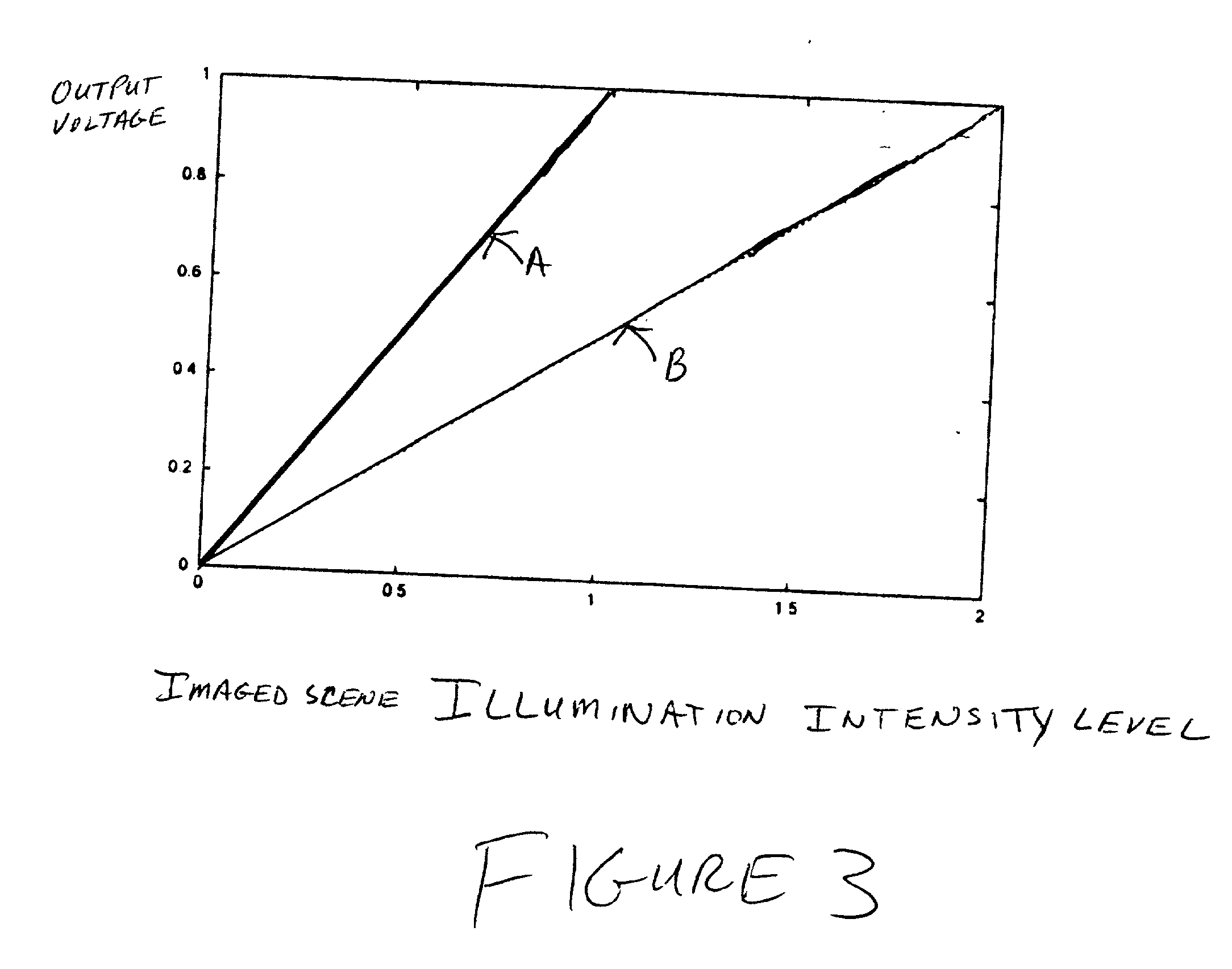
Using this conventional approach, a greater portion of the higher illumination intensity levels of the scene can be represented; however, the image is unacceptably dark, the quantization noise of the entire image has been cut in half, and the signal may also have been reduced by a factor of 2 while other noise sources stay fixed in magnitude (such as reset noise).

Method used


Image

  • Adaptive sensitivity control, on a pixel-by-pixel basis, for a digital imager
  • Adaptive sensitivity control, on a pixel-by-pixel basis, for a digital imager
  • Adaptive sensitivity control, on a pixel-by-pixel basis, for a digital imager

Examples


Embodiment Construction

[0050] It is desirable to increase the dynamic range of the digital imager such that the low illumination intensity levels of the scene are emphasized, but also the high illumination intensity levels of the scene are represented and no pixels become saturated during a given integration period. Moreover, it is desirable to utilize the entire dynamic range of the digital imager when imaging a scene, notwithstanding the actual range of illumination intensities of the scene.

[0051] The present invention provides techniques and systems for adjusting the sensitivity, on a pixel-by-pixel basis, of a digital imager by adjusting the transfer control function (resulting in the production of the control signal) through determining an illumination intensity level mapping function and an integration time characteristic of the digital imager in a manner that enables full use of the entire output intensity level range of the digital imager without saturation of the digital imager. These techniques ...


PUM


Abstract

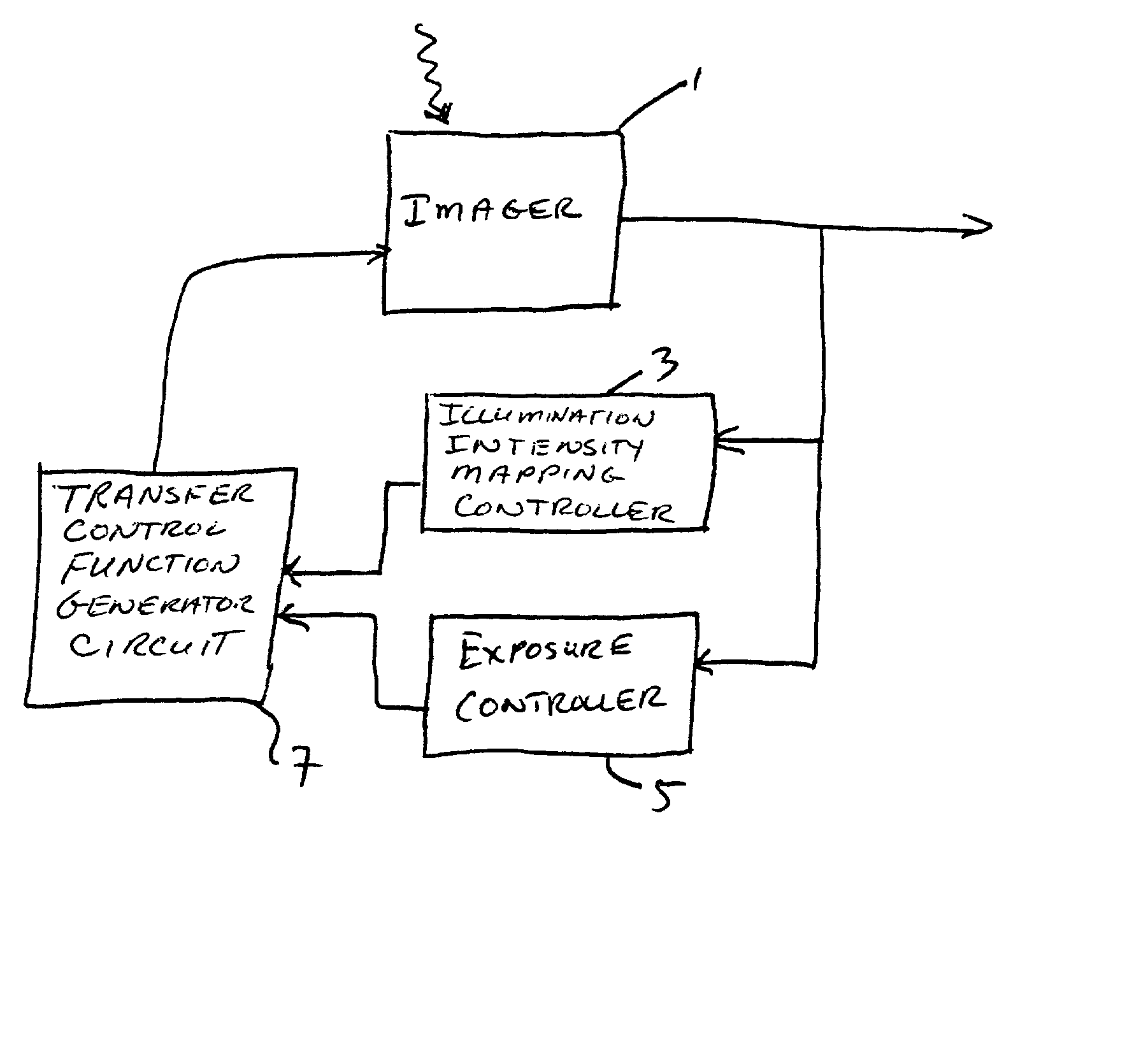
A system and method adaptively control sensitivity, on a pixel-by-pixel basis, of a digital imager. An illumination intensity level mapping controller determines a number of pixels of image data having illumination intensity levels within a first defined range of illumination intensity levels and determines an illumination intensity level mapping function based upon the determined number of pixels within the first defined range of illumination intensity levels. An exposure controller determines a number of pixels having illumination intensity levels within a second defined range of illumination intensity levels and determines an integration time based upon the determined number of pixels having illumination intensity levels within the second defined range of illumination intensity levels. A transfer control function generation circuit determines a composite transfer control function based on the determined integration time and determined illumination intensity level mapping function; determines each transition point between a plurality of discrete transfer control functions from the determined integration time and the determined illumination intensity level mapping function; and imposes the determined transfer control function upon a pixel of the digital imager.

Description

PRIORITY INFORMATION[0001] This application claims priority from U.S. Provisional Patent Application, Serial No. 60 / 261,023, filed on Jan. 11, 2001; the entire contents of which are hereby incorporated by reference.FIELD OF THE PRESENT INVENTION[0002] The present invention is directed to controlling sensitivity, on a pixel-by-pixel basis, of a digital imager. More specifically, the present invention is directed to adaptively controlling sensitivity, on a pixel-by-pixel basis, of a digital imager to expand a dynamic range of the digital imager.BACKGROUND OF THE PRESENT INVENTION[0003] Conventionally, digital imagers, as noted above, are characterized by a linear voltage-to-light response, or transfer function; that is, the digital imager output voltage is approximately linearly related to light incident on the digital imager. Specifically, the output voltage transfer function is linearly proportional to the intensity of the light incident upon the digital imager. This linear transfer...

Claims


Application Information

Patent Timeline
IPC IPC(8): H04N5/235H04N5/355H04N5/374
CPCH04N5/23225H04N5/23241H04N5/235H04N5/2353H04N5/35509H04N5/35527H04N5/374H04N2201/3252H04N23/617H04N23/65H04N23/70H04N23/73H04N25/571H04N25/575H04N25/76
Inventor MASAKI, ICHIROBROOKS, LANE GEARLESIKRI, VIVEK A.FIFE, KEITH GLEN
Owner SMAL CAMERA TECH
Learn More