Systems and methods for high-accuracy displacement determination in a correlation based position transducer

a position transducer and high-accuracy technology, applied in the field of image correlation, can solve the problems of insufficient consideration of the computational complexity and associated processing time required to reduce the computational complexity and the associated processing time, and the effect of preventing the position determination to a high resolution and accuracy in a commercially marketable form

Inactive Publication Date: 2002-08-08
MITUTOYO CORP
View PDF1 Cites 58 Cited by
  • Summary
  • Abstract
  • Description
  • Claims
  • Application Information

AI Technical Summary

Problems solved by technology

However, inboth conventional devices and laboratory systems that use image correlation in high-accuracy positioning and the like, the practical problems that effectively prevent determining position to a high resolution and accuracy in a commercially marketable form have not been adequately considered.
In particular, these conventional devices and high-accuracy laboratory systems and the like have given insufficient consideration to reducing the computational complexity and associated processing time required to determine the displacement to a sub-pixel resolution, while simultaneously achieving an accuracy that is on the same order as the resolution.
Furthermore, for all of the above-outlined conventional methods, it has been observed that systematic errors appear, and the accuracy and meaningful resolution degrades rapidly, when these above-outlined conventional methods are based on lower-order interpolation, relatively fewer discrete pixel-by-pixel points of a correlation function, or relatively fewer iterations of a procedure based on a reduced set of discrete pixel-by-pixel points of a correlation function.
Therefore, all of the above-outlined conventional methods are relatively computationally intensive.
Thus, the allowable displacement speed, resolution, and accuracy of these conventional systems is limited, especially in combination, and especially in an economical and convenient system of wide utility.
Such errors arise especially when a second image is displaced by a non-integer number of pixels relative to a first image.
Therefore, the assumed form of the function used for sub-pixel interpolation only approximates the actual function, and errors arise.

Method used


Image

  • Systems and methods for high-accuracy displacement determination in a correlation based position transducer
  • Systems and methods for high-accuracy displacement determination in a correlation based position transducer
  • Systems and methods for high-accuracy displacement determination in a correlation based position transducer

Examples


Embodiment Construction

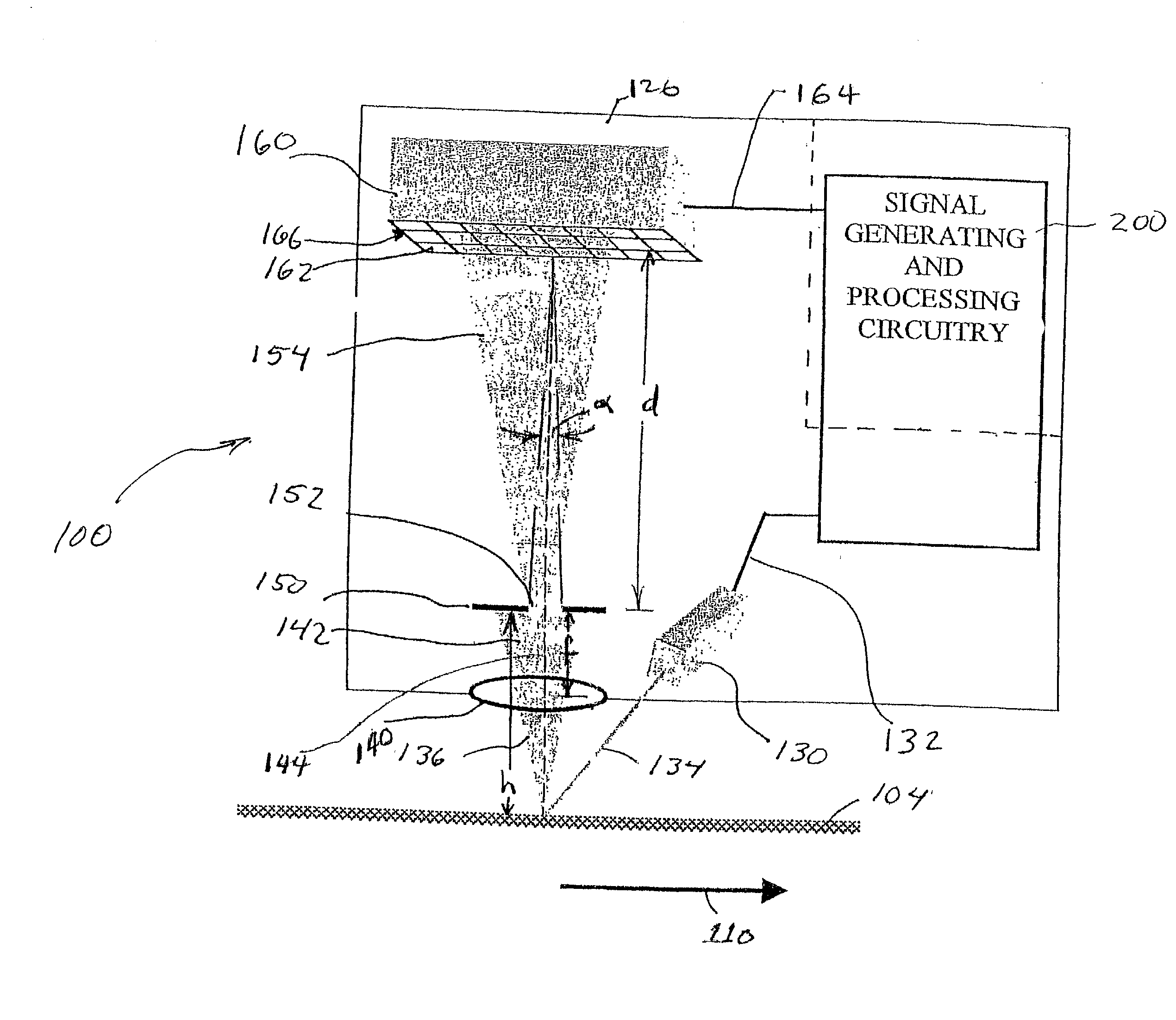
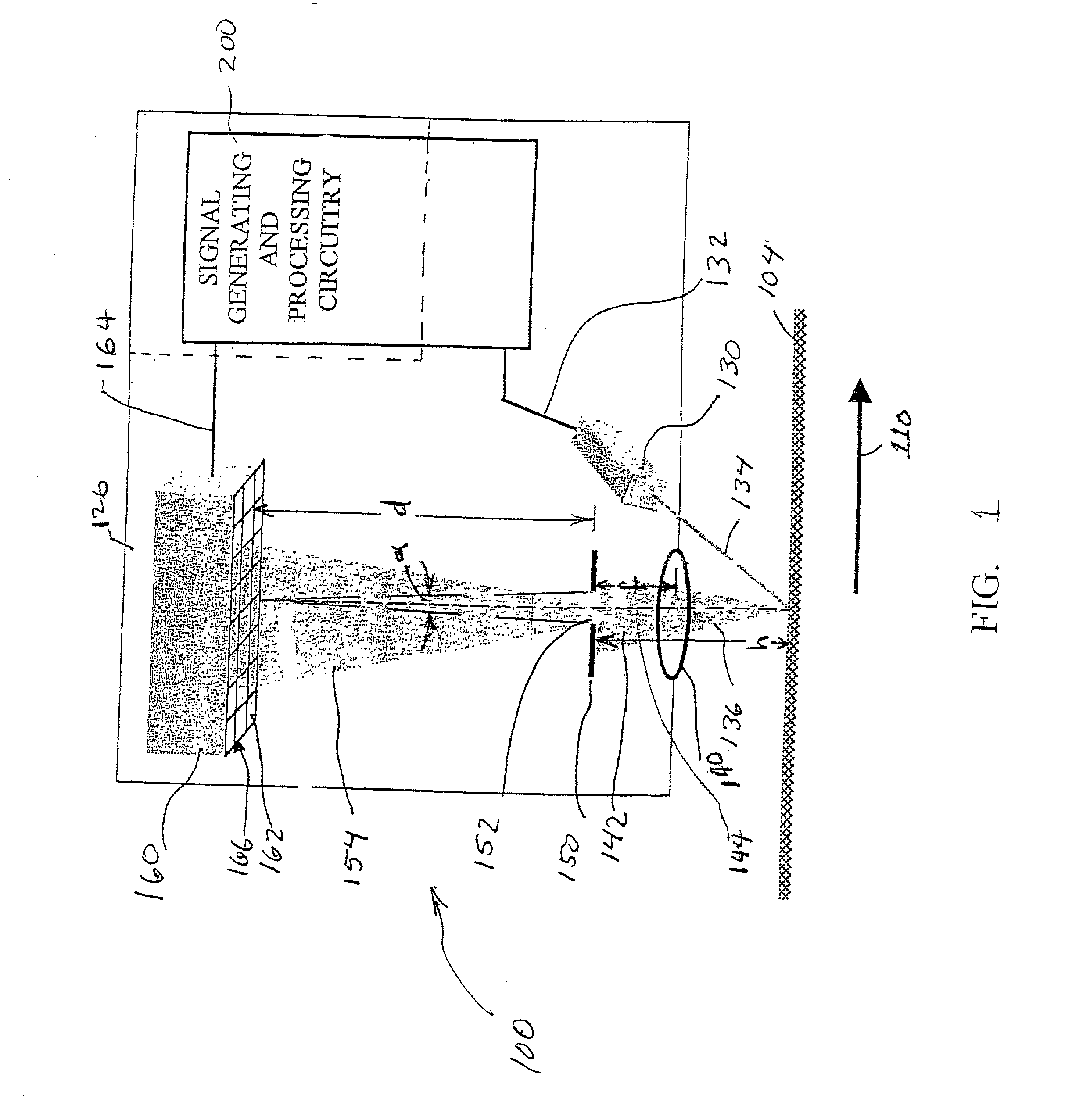
[0054] FIG. 1 is a block diagram of a speckle-image-based optical position transducer 100. The speckle-image-based optical position transducer 100, as well as various suitable mechanical and optical configurations, image correlation methods, and associated signal processing circuitry are described in greater detail in co-pending U.S. application Ser. No. 09 / 584,264, incorporated herein by reference in its entirety.

[0055] The speckle-image-based optical position transducer 100 shown in FIG. 1 includes a readhead 126, signal generating and processing circuitry 200 and an optically rough surface 104. In FIG. 1, the components of readhead 126, and their relation to the optically rough surface 104, are shown schematically in a layout that generally corresponds to an exemplary physical configuration, as further described below.

[0056] In particular, the optically diffusing, or optically rough, surface 104 is positioned adjacent to an illuminating and receiving end of the readhead 126, such...


PUM


Abstract

An image which is determined by surface is captured and stored by sensing device. Subsequently, at a second image corresponding to a displacement of the surface is captured and stored. The two images are repeatedly compared at different offsets in a displacement direction. Theoretically, the most extreme value of the comparison will occur at the image offset that corresponds exactly with the actual displacement. However, typically none of the comparison offsets correspond exactly with the actual displacement, therefore interpolation between the comparison offsets is required. The method of comparing the images, as well as the method of interpolating to determining the image offset corresponding to the extreme value of the comparison can both contribute to systematic errors in estimating the displacement of the surface from the images. Herein, the systematic errors are rejected by correlation-based comparison systems and methods which reduce the curvature of the correlation function for offsets which bound the extreme value, and by interpolation systems and methods which are relatively insensitive to the asymmetry of the correlation function value points selected as the basis for the interpolation. These systems and methods allow fast, highly accurate, displacement determinations using relatively simplified calculations and relatively few correlation function value points. Thus, such a displacement measuring system can track high speed displacements with high accuracy. The systems and methods are especially suitable for measuring displacement of a surface using speckle images.

Description

[0001] 1. Field of Invention[0002] This invention is directed to determining positional displacements using image correlation.[0003] 2. Description of Related Art[0004] Various known devices use images acquired by an sensor array, and correlation between images acquired by the sensor array to determine deformations and / or displacements. For example, one class of such devices is based on acquiring a speckle image generated by illuminating an optically rough surface with a light source. Generally, the light source is a coherent light source, such as a laser-generating light source. Such laser-generating light sources include, a laser, a laser diode, and the like. After the optically rough surface is illuminated by the light source, the light scattered from the optically rough surface is imaged onto an optical sensor. The optical sensor can be a charge-coupled device (CCD), or a semi-conductor image sensor array, such as a CMOS image sensor array, or the like.[0005] Prior to displacing...

Claims


Application Information

Patent Timeline
Patent Type & Authority Applications(United States)
IPC IPC(8): G06T7/60G01B11/00G01B11/14
CPCG01B11/00G01B11/14
Inventor NAHUM, MICHAELMAWET, PATRICK H.
Owner MITUTOYO CORP
Why Eureka
Try Eureka