
Method of detecting position of rotation axis of suction nozzle, and electric-component mounting system

a technology of suction nozzle and rotation axis, which is applied in the direction of metal-working machine components, instruments, manufacturing tools, etc., can solve the problems of deformation of the machine frame of the electric-component mounting system, the deformation of the brackets holding the image-taking devices, and the position errors of the electric components

Inactive Publication Date: 2002-08-15
FUJI MASCH MFG CO LTD
View PDF3 Cites 25 Cited by
  • Summary
  • Abstract
  • Description
  • Claims
  • Application Information

AI Technical Summary

Benefits of technology

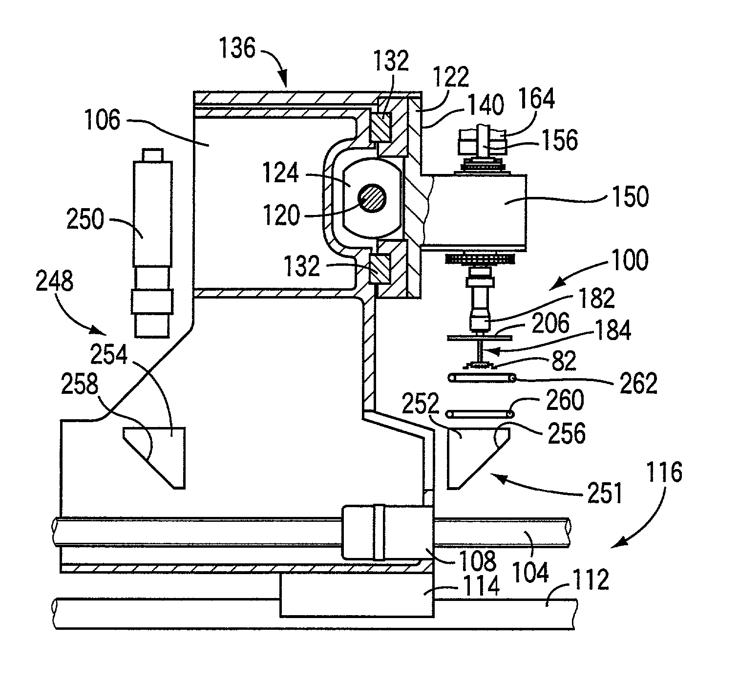
[0028] The calibration member may have the support surface literally level with the position-detecting plane, and has at least one first positioning reference on at least one reference surface more or less vertically distant from the position-detecting plane, e.g., by a distance equal to a thickness of the calibration gauge. The step of detecting the position may comprise repeating, at least one more time, the step of holding the calibration gauge, the step of rotating the suction nozzle, the step of placing the calibration gauge, and the step of taking the second mage, and the step of processing the first and second images may comprise processing the first image and at least two second images to determine the relative position between the reference point of the calibration member and the position of the rotation axis of the suction nozzle. According to this feature, the position of the rotation axis of the suction nozzle can be detected on the plane including the component-mounting surface of the circuit substrate. In addition, an error of a relative position between the rotation axis of the nozzle and the image-taking device can be detected while the first positioning reference of the calibration member is used as a parameter. According to this feature, it is preferred to use, as the image-taking device, a fiducial-mark-image taking device employed for taking an image of at least one fiducial mark provided on the circuit substrate. In the latter case, an error of a relative position between the rotation axis of the suction nozzle and the fiducial-mark-image taking device can be detected easily and accurately.
[0038] The present method may further comprises repeating, at least one more time, the step of holding the calibration gauge, the step of rotating the suction nozzle, the step of placing the calibration gauge, and the step of taking the second mage, and the step of processing the first and second images may comprise processing the first image and at least two second images to determine the relative position between the reference point of the calibration member and the position of the rotation axis of the suction nozzle. According to this invention, an error of a relative position between the fiducial-mark-image taking device and the rotation axis of the suction nozzle can be detected easily and accurately. It is noted that according to this invention, it is not essentially required that the support surface of the calibration member should be provided on the plane including the component-mounting surface of the circuit substrate.
[0040] For example, respective edge lines of the calibration member and the calibration gauge may be utilized as respective positioning references and respective images of those edge lines may be taken. However, according to the fifth feature (5), respective positions of the calibration member and the calibration gauge can be more easily and accurately detected based on the reference marks provided on the surface.
[0046] Since the calibration gauge has the reference marks on the upper surface thereof level with an upper surface of the calibration gauge, a sharp or clear image of the respective reference marks of the calibration member and the calibration gauge can be taken at one time and accordingly the accuracy of detection of positions can be easily improved.
[0048] Since the calibration gauge is held, by suction, by the support surface of the calibration member, the gauge is effectively prevented from moving out of position relative to the calibration member. Accordingly, for example, an error of a relative position between the rotation axis of the suction nozzle and the calibration member, and an error of a relative position between the rotation axis of the suction nozzle and the fiducial-mark-image taking device can be accurately detected.
[0052] According to this feature, an error of a relative position between the calibration member and the fiducial-mark-image taking device can be accurately detected.

Problems solved by technology

The positioning error includes at least one of an error of positioning of the center position or other reference position of the electric component in a plane perpendicular to an axis of rotation of the suction nozzle, and an error of angular positioning of the electric component about the axis of rotation of the suction nozzle.
The positioning errors of the electric component and the fiducial marks may be obtained by detecting those relative positions using exclusively designed detecting devices, when the electric-component mounting system is assembled or inspected for maintenance purposes.
To obtain the positioning errors in this manner, the detecting devices are required to be complicated and tend to be expensive.
In addition, the machine frame of the electric-component mounting system, brackets which hold the image-taking devices, and other portions of the system are also subject to deformation due to a temperature variation.
However, such measures inevitably result in an increase in the cost of manufacture of the electric-component mounting system, and cannot therefore be said to be completely satisfactory.
Therefore, while the suction nozzle is lowered from the first position to the second position, the position of the rotation axis of the suction nozzle more or less changes, which is considered as one of various causes to lower the component mounting accuracy.

Method used


Image

  • Method of detecting position of rotation axis of suction nozzle, and electric-component mounting system
  • Method of detecting position of rotation axis of suction nozzle, and electric-component mounting system
  • Method of detecting position of rotation axis of suction nozzle, and electric-component mounting system

Examples


Embodiment Construction

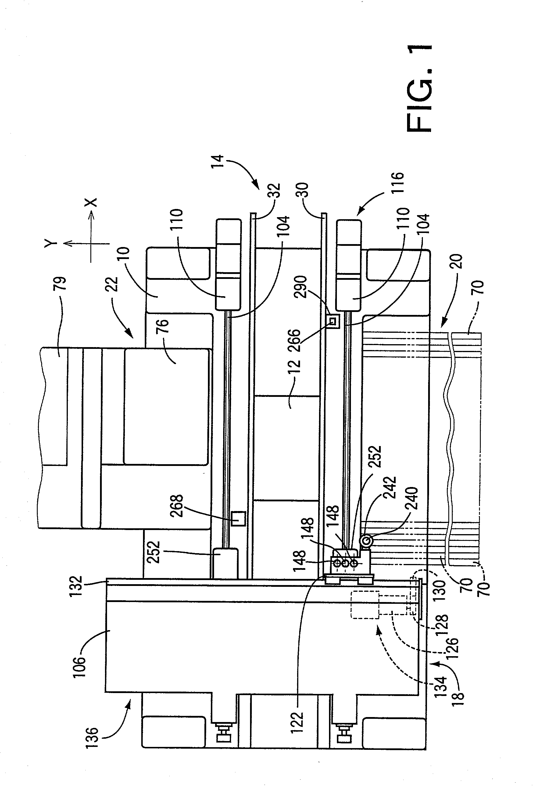
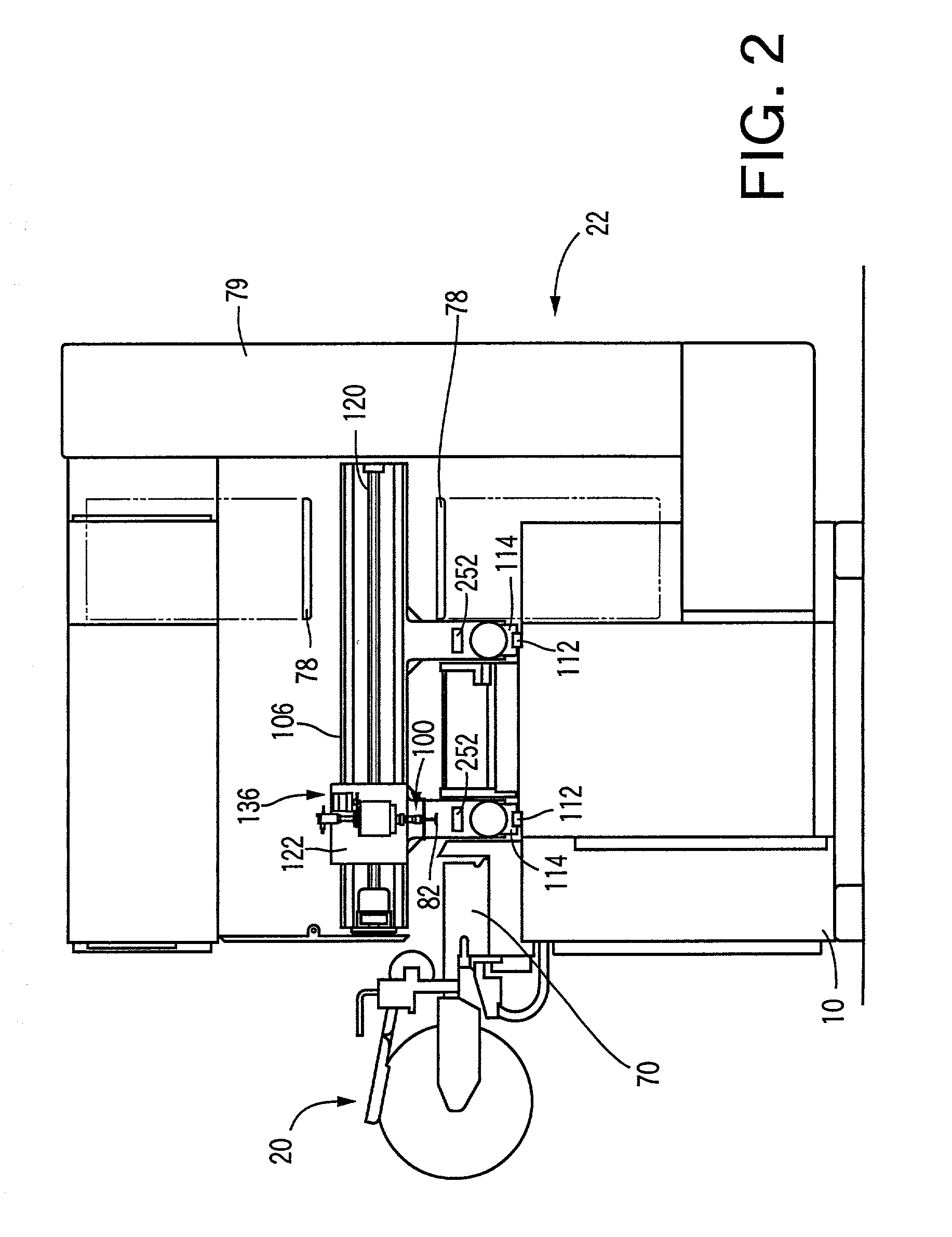
[0089] Referring first to FIGS. 1 and 2, reference numeral 10 denotes a machine base of an electronic-component mounting system. The electronic-component mounting system includes a printed-wiring board conveyor (PWB conveyor) 14, a component mounting device 18 and component supply devices 20, 22, which are mounted on the machine base 10. The PWB conveyor 14 is arranged to transfer a circuit substrate in the form of a printed-wiring board 12 in an X-axis direction (in the left and right directions as seen in FIG. 1). The component mounting device 18 is arranged to mount electric components in the form of electronic components on the printed-wiring board 12. The component supply devices 20, 22 are arranged to supply the component mounting device 18 with the electronic components.

[0090] In the present embodiment, the printed-wiring board 12 is transferred by the PWB conveyor 14 such that the printed-wiring board 12 maintains a horizontal attitude or posture. The printed-wiring board 12...


PUM

PropertyMeasurementUnit
Timeaaaaaaaaaa
Timeaaaaaaaaaa
Thicknessaaaaaaaaaa

Abstract

A method of detecting a position of a rotation axis of a suction nozzle of an electric-component mounting apparatus, the suction nozzle holding, by suction, an electric component, and being rotated about the rotation axis thereof to rotate the electric component held thereby, so that the electric component rotated is mounted on a component-mounting surface of a circuit substrate, the method including the step of detecting, on a position-detecting plane including the component-mounting surface of the circuit substrate, the position of the rotation axis of the suction nozzle.

Description

[0001] 1. Field of the Invention[0002] The present invention relates to an electric-component mounting system arranged to mount electric components (including electronic components) on a circuit substrate such as a printed-wiring board, and to a method of obtaining relative positions of specific sections of the electric-component mounting system that influence the accuracy of mounting of the electric components.[0003] 2. Discussion of Related Art[0004] Electric-component mounting systems often use a suction nozzle arranged to hold an electric component by suction under a negative pressure. Usually, the actual position of the electric component held by the suction nozzle deviates from the nominal position. In view of this positional deviation of the electric component, it has been practiced to detect an error of positioning of the electric component with respect to the suction nozzle by operating an image-taking device to take an image of the electric component as held by the suction...

Claims


Application Information

Patent Timeline
IPC IPC(8): H05K13/04
CPCH05K13/0413Y10T29/53191Y10T29/53178Y10T29/53087Y10T29/49131Y10T29/4913Y10T29/49133H05K13/089
Inventor ISOGAI, TAKEYOSHIYASUDA, KIMIHIKOIWAKI, NORIAKIKATSUMI, HIROSHI
Owner FUJI MASCH MFG CO LTD
Learn More