Low cost microstrip antenna

a microstrip antenna and low cost technology, applied in the direction of resonant antennas, substantially flat resonant elements, radiating element structural forms, etc., can solve the problems of inconvenient use of low-cost omni-directional antennas, insufficient resonant frequency, and insufficient resonant frequency

Inactive Publication Date: 2002-08-15
MAXRAD +1
View PDF5 Cites 102 Cited by
  • Summary
  • Abstract
  • Description
  • Claims
  • Application Information

AI Technical Summary

Problems solved by technology

However, fixed radio systems can take advantage of antennas structures with higher gain and directivity to improve system performance, so the low cost omni-directional antennas are not suitable.
Therefore, the cost of such antennas is too high, and out of proportion with the system cost generally.

Method used


Image

  • Low cost microstrip antenna
  • Low cost microstrip antenna
  • Low cost microstrip antenna

Examples


Embodiment Construction

[0017] Illustrative embodiments and exemplary applications will now be described with reference to the accompanying drawings to disclose the advantageous teachings of the present invention.

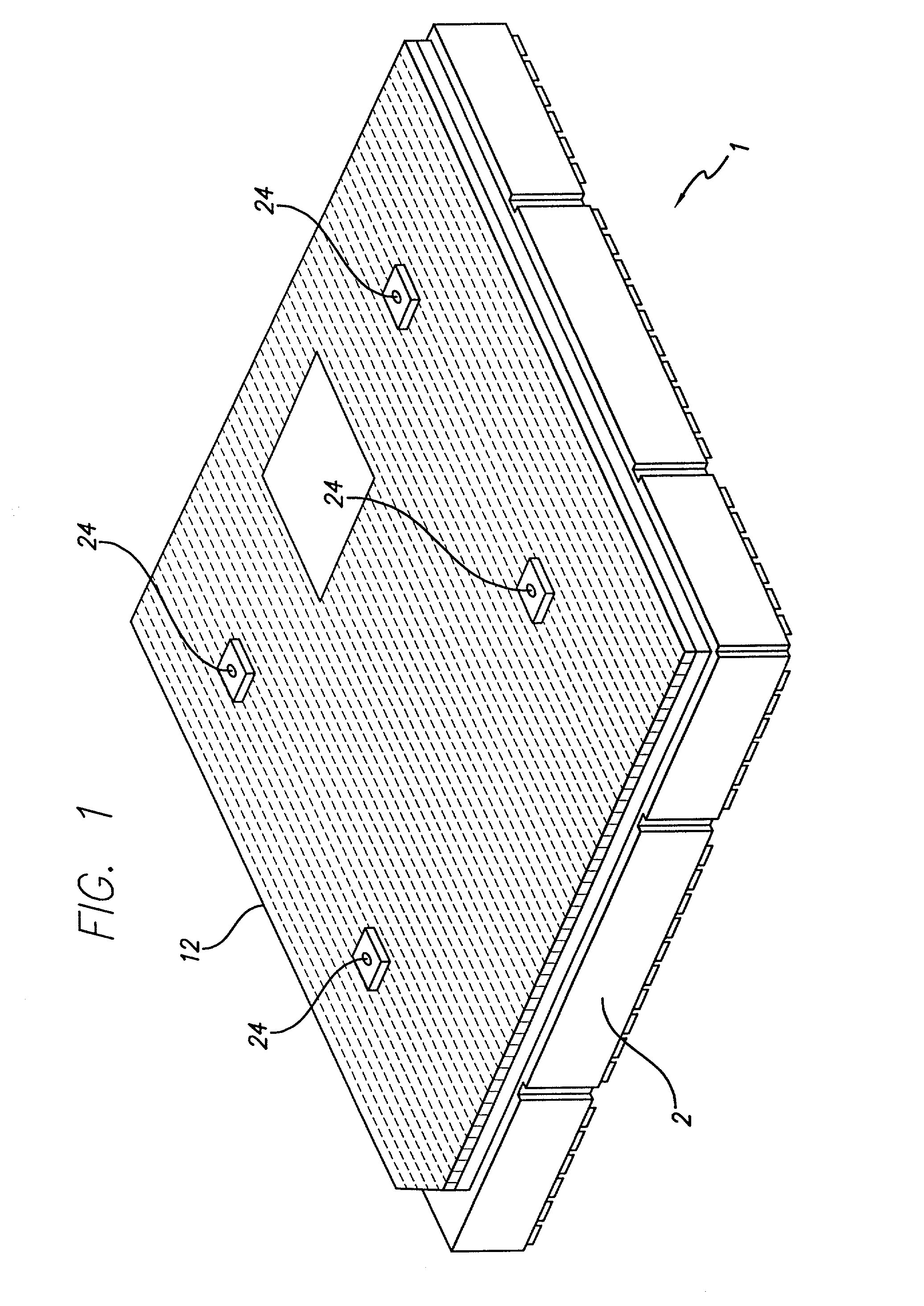
[0018] Reference is directed to FIG. 1 which is an isometric view of the assembled microstrip antenna 1 in the preferred embodiment. The antenna shield 2 forms the foundation of the antenna and is fabricated from metal or metalized plastic so as to form a conductive, planar, surface onto which the other antenna elements are assembled by stacking. The stack of antenna elements (not clearly shown in this view) is covered and protected by a rigid plastic cover support 12 which is held in place by plastic fasteners 24.

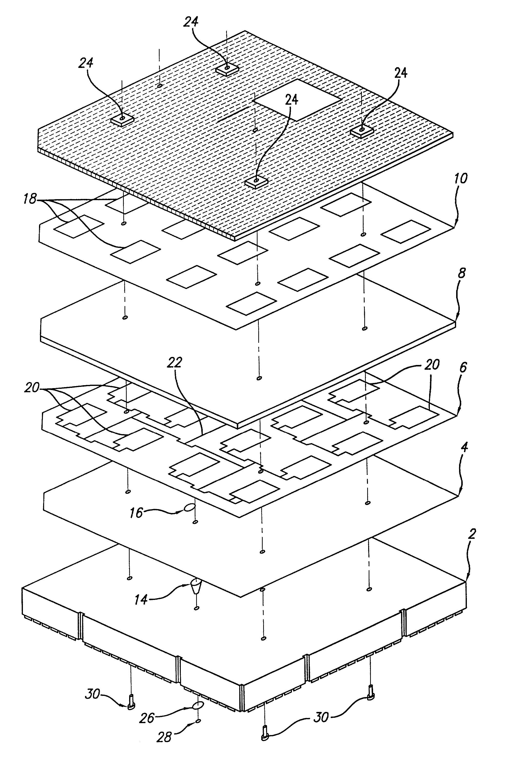
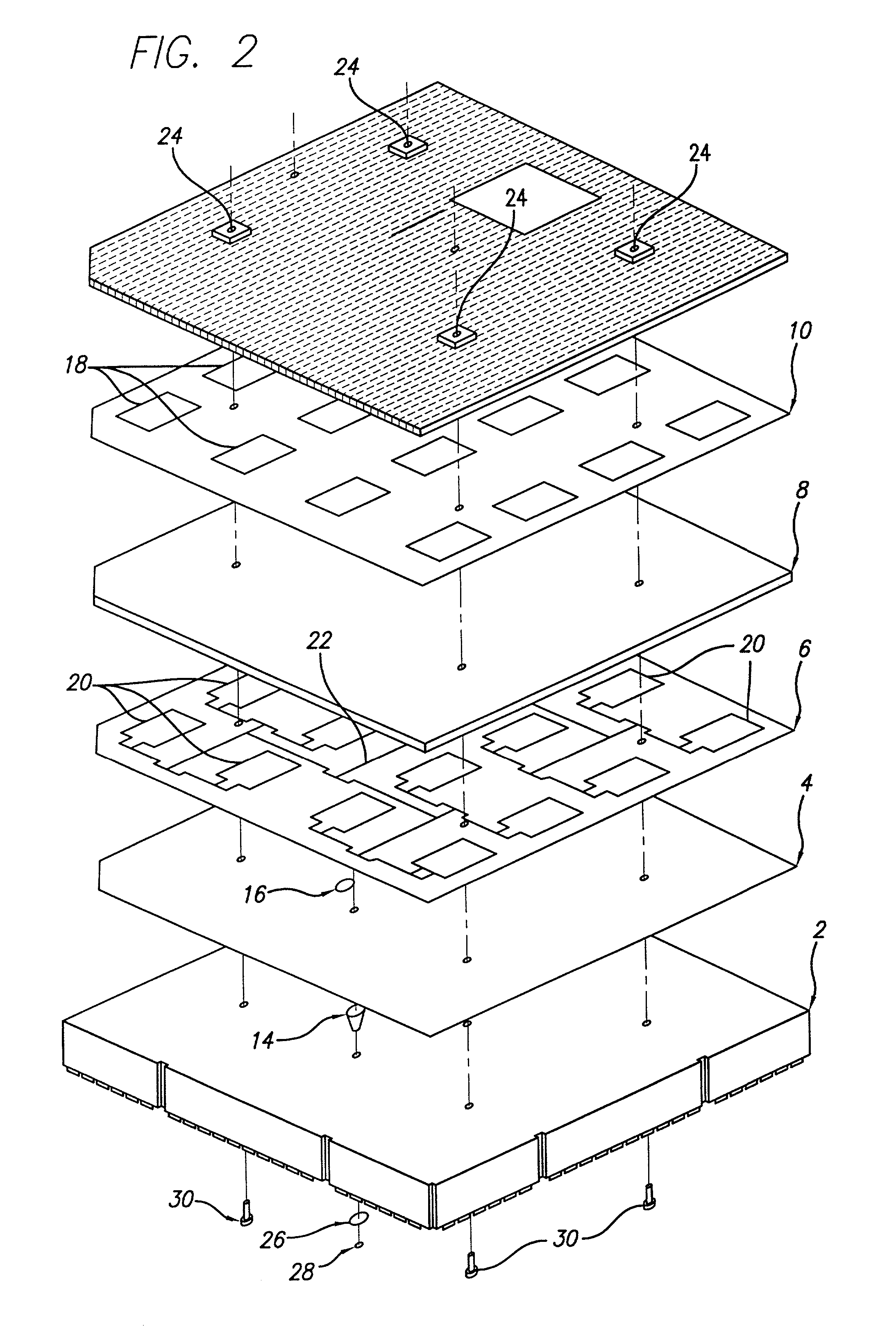
[0019] FIG. 2 illustrates an exploded isometric view of the microstrip antenna 1 in the preferred embodiment. The antenna shield 2 has a rigid metal or metalized planar surface on its top which forms the platform onto which the other antenna elements are stacked. To facilitate coupling o...


PUM


Abstract

An low cost stacked microstrip antenna and low cost method of making the same are disclosed. By using specially designed bandwidth and directivity parameters in conjunction with lower cost dielectric, materials economies of production are realized. In particular, dielectric support layers made from fine cell foam sheet material that is mass produced for primary purposes other than electrical insulation materials, are used to reduce cost. A stackable design used in conjunction with a capacitively coupled feedline connector reduce assembly costs as well.

Description

[0001] 1. Field of the Invention[0002] The present invention relates to antennas. More specifically, the present invention relates to low cost microstrip antennas designed and manufactured using a stack of components.[0003] While the present invention is described herein with reference to illustrative embodiments for particular applications, it should be understood that the invention is not limited thereto. Those having ordinary skill in the art and access to the teachings provided herein will recognize additional modifications, applications, and embodiments within the scope thereof and additional fields in which the present invention would be of significant utility.[0004] 2. Description of the Related Art[0005] Microstrip antennas are well known in the art. Microstrip antennas generally operate in VHF, UHF, and higher frequency ranges where the electromagnetic wavelengths are short enough to allow relatively compact resonant structures to act as transmitting and receiving antennas....

Claims


Application Information

Patent Timeline
Patent Type & Authority Applications(United States)
IPC IPC(8): H01Q9/04H01Q21/00
CPCH01Q9/0407H01Q21/0087
Inventor OW, STEVENCONNOLLY, PETERMCCARTHY, ROBERT
Owner MAXRAD
Why Eureka
Try Eureka