
Long subscriber loops using modified load coils

a technology of load coils and subscriber loops, applied in the field of communications, can solve the problems of limited data rate of such transmission, analog nature of older central office switches, and inability to provide a broad range of services, and achieve the effect of dsls, and reducing the number of dsls

Inactive Publication Date: 2002-08-22
SYMMETRICOM
View PDF3 Cites 15 Cited by
  • Summary
  • Abstract
  • Description
  • Claims
  • Application Information

AI Technical Summary

Benefits of technology

[0079] A digital subscriber loop repeater, representing an embodiment of the invention can be cost effective and advantageous for at least the following reasons. The invention permits DSL to be provided on long loops. The invention permits DSL to be provided on loaded loops. The new scheme is especially appropriate for providing ADSL over long subscriber loops which require "repeaters" or "extenders". While conventional DSL installation requires that all load coils be removed from a loop, the invention can include the replacement of these load coils with what can be termed to be "a modified load coil circuit." In addition, the invention improves quality and / or reduces costs compared to previous approaches.[0080] All the disclosed embodiments of the invention disclosed herein can be made and used without undue experimentation in light of the disclosure. Although the best mode of carrying out the invention contemplated by the inventors is disclosed, practice of the invention is not limited thereto. Accordingly, it will be appreciated by those skilled in the art that the invention may be practiced otherwise than as specifically described herein.[0081] Further, the individual components need not be formed in the disclosed shapes, or combined in the disclosed configurations, but could be provided in virtually any shapes, and / or combined in virtually any configuration. Further, the individual components need not be fabricated from the disclosed materials, but could be fabricated from virtually any suitable materials.[0082] Further, variation may be made in the steps or in the sequence of steps composing methods described herein. Further, although the digital subscriber loop repeaters described herein can be separate modules, it will be manifest that the repeaters may be integrated into the system with which they are associated. Furthermore, all the disclosed elements and features of each disclosed embodiment can be combined with, or substituted for, the disclosed elements and features of every other disclosed embodiment except where such elements or features are mutually exclusive.[0083] It will be manifest that various substitutions, modifications, additions and / or rearrangements of the features of the invention may be made without deviating from the spirit and / or scope of the underlying inventive concept. It is deemed that the spirit and / or scope of the underlying inventive concept as defined by the appended claims and their equivalents cover all such substitutions, modifications, additions and / or rearrangements.[0084] The appended claims are not to be interpreted as including means-plus-function limitations, unless such a limitation is explicitly recited in a given claim using the phrase(s) "means for" and / or "step for." Subgeneric embodiments of the invention are delineated by the appended independent claims and their equivalents. Specific embodiments of the invention are differentiated by the appended dependent claims and their equivalents.

Problems solved by technology

Older central office switches were analog in nature and were unable to provide a broad range of services.
Because of the 4 kHz constraint imposed by the A / D converter in the line circuit, the data rate of such transmission is limited and is typically 9.6 kbps.
With increasing deployment of, and consequently demand for, digital services it is clear that this bit rate is insufficient.
A stumbling block in specifying, or guaranteeing, a definite bit rate to a customer is the nature of the loop plant.
The essentially lowpass frequency response of subscriber cable limits the usable bandwidth and hence the bit rate.
In these loaded loops, the spectral region above 10 kHz is unusable for reliable transmission.
Heretofore, there has not been a completely satisfactory approach to providing DSL over long loops.
Further, there has not been a satisfactory approach to providing DSL over loaded loops.

Method used


Image

  • Long subscriber loops using modified load coils
  • Long subscriber loops using modified load coils
  • Long subscriber loops using modified load coils

Examples


Embodiment Construction

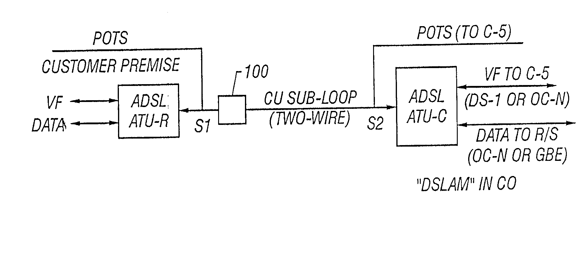
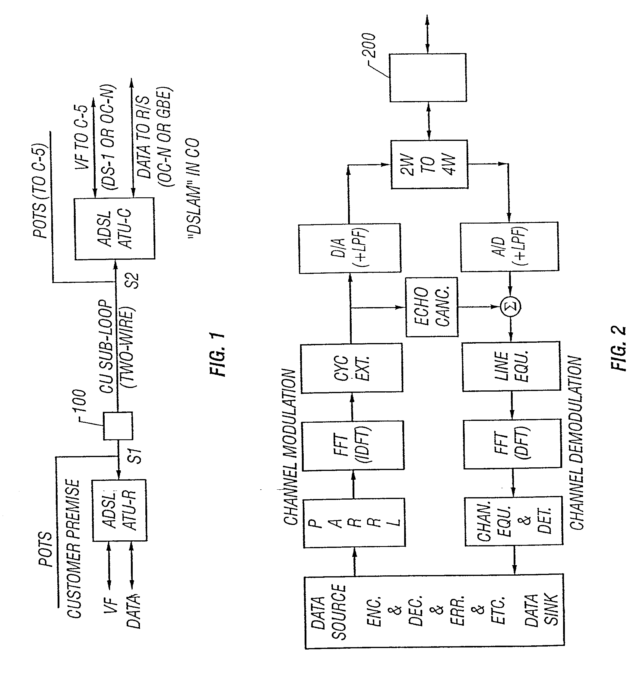
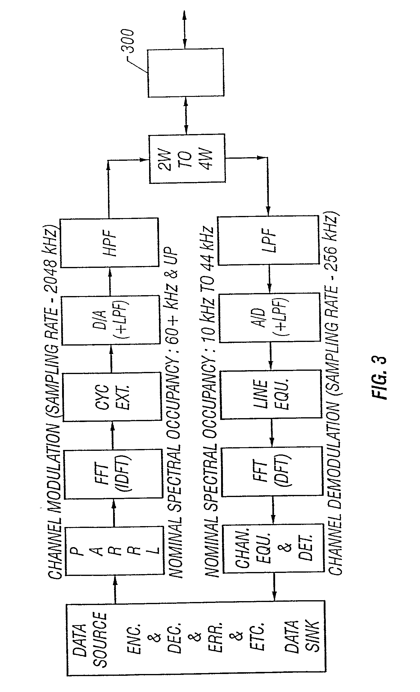
[0025] The invention and the various features and advantageous details thereof are explained more fully with reference to the nonlimiting embodiments that are illustrated in the accompanying drawings and detailed in the following description. Descriptions of well known components and processing techniques are omitted so as not to unnecessarily obscure the invention in detail. It should be understood, however, that the detailed description and the specific examples, while indicating preferred embodiments of the invention, are given by way of illustration only and not by way of limitation. Various substitutions, modifications, additions and / or rearrangements within the spirit and / or scope of the underlying inventive concept will become apparent to those skilled in the art from this detailed description.

[0026] Within this application several publications are referenced by Arabic numerals within parentheses or brackets. Full citations for these, and other, publications may be found at t...


PUM


Abstract

Systems and methods are described for long subscriber loops using modified load coils. A method includes providing a circuit to extend a transmission medium, the circuit including an inductor and a shunt network, the inductor including a first leg and a second leg, the shunt network including a first circuit portion and a second circuit portion, the first circuit portion including a first capacitor and a first resistor, the first capacitor disposed in a parallel relationship across the first leg of the inductor, the first resistor disposed in a parallel relationship across the first leg of the inductor, the second circuit portion including a second capacitor and a second resistor, the second capacitor disposed in a parallel relationship across the second leg of the inductor, the second resistor disposed in a parallel relationship across the second leg of the inductor; providing an inductive admittance from the first leg of the inductor to a first communication transmitted within a first frequency band; and providing a capacitive admittance from the first circuit portion of the shunt network to a second communication transmitted within a second frequency band. An apparatus includes a circuit including an inductor and a shunt network, the inductor having a first leg and a second leg, the shunt network including a first circuit portion and a second circuit portion, the first circuit portion including a first capacitor and a first resistor, the first capacitor disposed in a parallel relationship across the first leg of the inductor, the first resistor disposed in a parallel relationship across the first leg of the inductor, and the second circuit portion including a second capacitor and a second resistor, the second capacitor disposed in a parallel relationship across the second leg of the inductor, the second resistor disposed in a parallel relationship across the second leg of the inductor, the first leg of the inductor provides an inductive admittance to a first communication transmitted within a first frequency band, and the first circuit portion of the shunt network provides a capacitive admittance to a second communication transmitted within a second frequency band.

Description

[0001] This application is related to, and claims a benefit of priority under 35 U.S.C. 119(e) and / or 35 U.S.C. 120 of copending U.S. Ser. No. 60 / 197,993, filed Apr. 18, 2000, now pending, the entire contents of which are hereby incorporated by reference for all purposes.[0002] 1. Field of the Invention[0003] The invention relates generally to the field of communications. More particularly, the invention relates to digital subscriber loop (DSL) communications. Specifically, a preferred implementation of the invention relates to extending the range of an asymmetric digital subscriber loop (ADSL). The invention thus relates to ADSL of the type that can be termed extended.[0004] 2. Discussion of the Related Art[0005] Conventional telephony, often called plain old telephone service (POTS), is provided to customers over copper cable. This copper cable can be termed a subscriber loop or a subscriber line. Modern loop plant designs specify the use of 26-gauge cable for short to medium loop...

Claims


Application Information

Patent Timeline
Patent Type & Authority Applications(United States)
IPC IPC(8): H04B3/26H04L27/26H04M7/00
CPCH04B3/26H04L27/2601
Inventor TAMBE, ATUL ANILSHENOI, KISHANBOGARDUS, GARY
Owner SYMMETRICOM
Learn More