Adaptive modulation communication system

Inactive Publication Date: 2002-08-22
PANASONIC CORP
View PDF12 Cites 34 Cited by
  • Summary
  • Abstract
  • Description
  • Claims
  • Application Information

AI Technical Summary

Benefits of technology

0017] It is an object of the present invention to provide an adaptive modulation communication system enabling excellent demodulat

Problems solved by technology

However, in the conventional adaptive modulation communication system, the receiving-side apparatus is not capable of demodulating data unless the transmitting-side notifies the receiving-side apparatus of the information on the modulation scheme (modulation level broadcast signal).
Further, demodulating data is started only after the modulation level broadcast signal is d

Method used


Image

  • Adaptive modulation communication system
  • Adaptive modulation communication system
  • Adaptive modulation communication system

Examples


first embodiment

[0043] (First Embodiment)

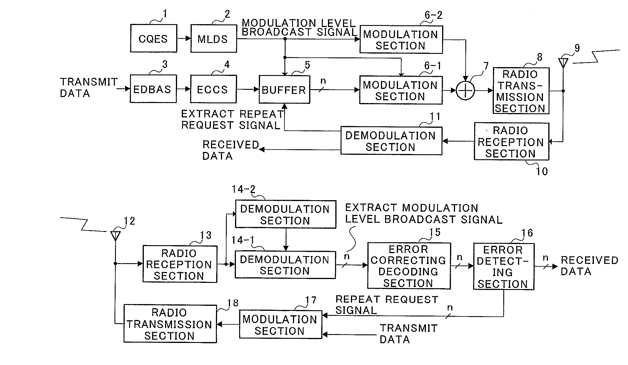
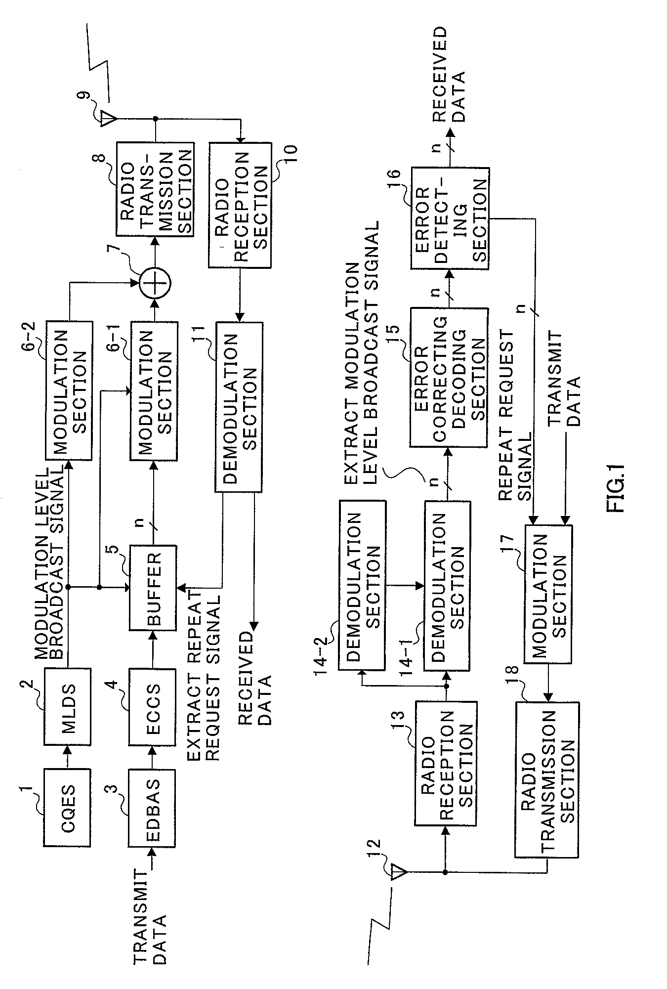
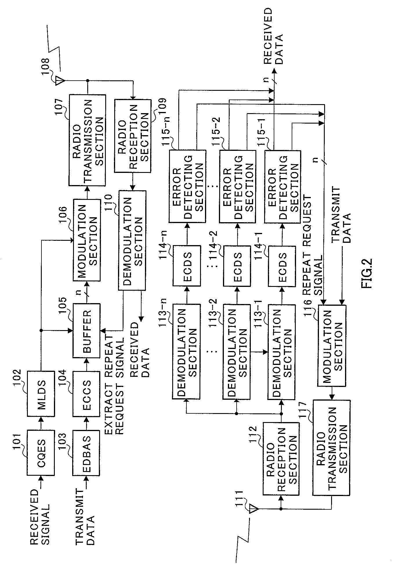
[0044] FIG. 2 is a block diagram illustrating a configuration of an adaptive modulation communication system according to the embodiments of the present invention.

[0045] In the adaptive modulation communication system illustrated in FIG. 2, CQES(channel quality estimating section) 101 in a transmitting-side apparatus estimates a channel quality using a received signal. The estimated channel quality information is output to MLDS(modulation level determining section) 102. MLDS 102 determines a modulation level based on the channel quality information. For example, when the channel quality is good, MLDS 102 increases the modulation level, while decreasing the modulation level when the channel quality is poor. The information on the modulation level is output to buffer 105, while being output to modulation section 106.

[0046] Transmit data is output to EDBAS(error detecting bit adding section) 103, where an error detecting bit is added for each predetermined unit...

second embodiment

[0099] (Second Embodiment)

[0100] This embodiment describes a case of applying to modulation schemes where a square root of the number of total signal points is not an integer, for example, 32QAM, 8QAM, and BPSK.

[0101] Generally, in such modulation schemes, as illustrated by broken line in FIGS. 11, 13 and 15, signal points are arranged in the form of a circle. In an adaptive modulation communication system according to this embodiment, the signal point arrangement in 32QAM is set as illustrated in FIG. 11 with eight points in the I(in-phase)-axis direction and with four points in the Q(quadrature)-axis direction. The signal point arrangement in 8QAM is set as illustrated in FIG. 13 with four points in the I-axis direction and with two points in the Q-axis direction. The signal point arrangement in BPSK is set as illustrated in FIG. 15 with two points in the I-axis direction. In other words, the number of signal points in the I-axis direction is made different from the number of sign...

third embodiment

[0127] (Third Embodiment)

[0128] This embodiment describes a case of applying the adaptive modulation communication system of the present invention to star-16QAM and 16PSK modulation schemes. Herein, the case will be described of applying the adaptive modulation communication system of the present invention to star-16QAM and 16PSK modulation schemes, using 8PSK.

[0129] FIG. 17 is a diagram to explain a signal space diagram of QPSK. FIG. 18 is a diagram to explain a signal space diagram of 8PSK. In FIG. 17, with respect to a first bit (upper bit), such bits are "0" above horizontal axis 1602, while being "1" under horizontal axis 1602, with axis 1602 as a boundary. With respect to a second bit (lower bit), such bits are "0" at the left of vertical axis 1601, while being "1" at right of vertical axis 1601, as viewed in the figure, with vertical axis 1601 as a boundary. Accordingly, by determining the foregoing, it is possible to demodulate 2 bits of QPSK.

[0130] In FIG. 18, the most sign...


PUM


Abstract

In an adaptive modulation communication system that adaptively varies a modulation scheme for each transmit unit, a transmitting-side apparatus sets different error detecting units corresponding to bit position, and transmits data subjected to error detecting processing on a different error detecting unit basis corresponding to bit position, and a receiving-side apparatus performs demodulation independently for each of the error correcting units using different demodulation patterns to obtain received data.

Description

[0001] The present invention relates to a new adaptive modulation communication system used in a digital radio communication system.[0002] With recent advances in internet-related techniques, the internet has enabled various services such as music distribution to be provided. Such services increase downlink transmit amounts. In order to achieve such services having increased transmit amounts, great expectations are placed on fast transmission over the downlink, and various techniques have been developed on the downlink fast transmission. One of the techniques is an adaptive modulation communication system where on a transmitting side a modulation scheme is adaptively varied to perform efficient data transmission.[0003] A conventional adaptive modulation communication system will be described with reference to FIG. 1.[0004] In the adaptive modulation communication system illustrated in FIG. 1, CQES(channel quality estimating section) 1 in a transmitting-side apparatus estimates a cha...

Claims


Application Information

Patent Timeline
IPC IPC(8): H04L1/00H04L1/18H04L27/00H04L27/18H04L27/34
CPCH04L1/0058H04L1/1867H04L27/0008H04L27/183H04L27/3488H04L27/00
Inventor UESUGI, MITSURUKATO, OSAMUUE, TOYOKI
Owner PANASONIC CORP
Why Eureka
Try Eureka