Pressure device and system for preventing thrombosis

a technology of thrombosis and pressure device, which is applied in the direction of vibration massage, aircraft crew accommodation, seating arrangements, etc., can solve the problems of dvt, potentially fatal blood clot formation, serious illness or even death

Inactive Publication Date: 2002-08-22
KUSLICH STEPHEN D +1
View PDF5 Cites 84 Cited by
  • Summary
  • Abstract
  • Description
  • Claims
  • Application Information

AI Technical Summary

Problems solved by technology

While several factors, such as advanced age, a persons weight, and other health characteristics may increase or decrease the likelihood of DVT occurring, extended periods of immobility, are a likely cause of DVT occurring in the legs.
If a person does suffer from DVT, a potentially fatal blood clot could form which may be large enough that the clot does not naturally dissolve.
Such a clot may break loose and travel from the person's leg to their heart or lungs resulting in serious illness or even death.
Unfortunately, under many circumstances a persons mobility may be limited to such an extent that walking around is not possible or is undesirable.
For example, as airlines attempt to force more and more seats onto a plane, not only are the seats more cramped but the isles are reduced in size, thus reducing the ability of a passenger to move about.
Unfortunately, compression stockings do not provide a flexing or pumping action to the legs to actively stimulate blood flow as is desired.
Of the various chambered sleeve devices described above, none of the devices described appear to be suitable for use en mass by passengers on an airplane.
The devices, their control systems and the equipment required to inflate the devices would be prohibitively bulky, heavy, and potentially dangerous in the controlled environment of an aircraft.
An additional problem with current devices is the need to include an electronic power supply which could interfere with the radio frequency used by the aircraft of an aircraft resulting in potentially fatal consequences for those on board.
Presently there does not exist an anti-thrombosis device which is suitable for use for individuals traveling on vehicles, such as airplanes.

Method used


Image

  • Pressure device and system for preventing thrombosis
  • Pressure device and system for preventing thrombosis
  • Pressure device and system for preventing thrombosis

Examples


Embodiment Construction

is hereafter described with specific reference being made to the drawings.

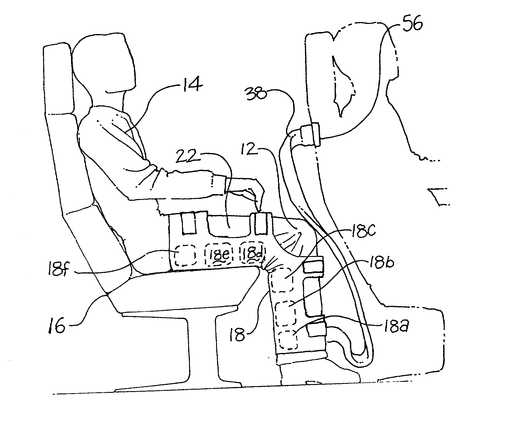
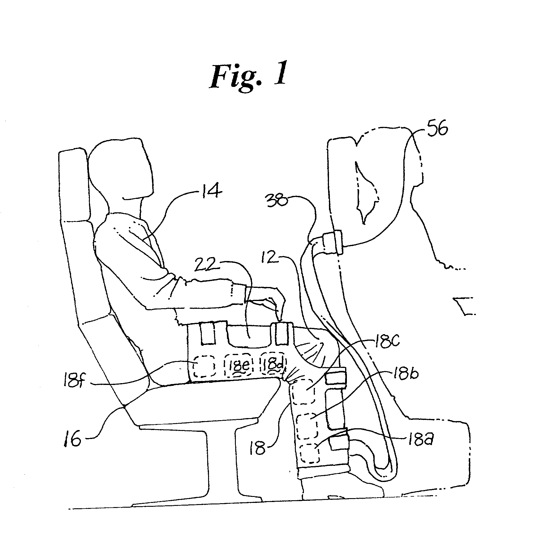
[0034] FIG. 1 is a side view of an embodiment of an inflatable sleeve which may be utilized in at least one embodiment of the inventive system.

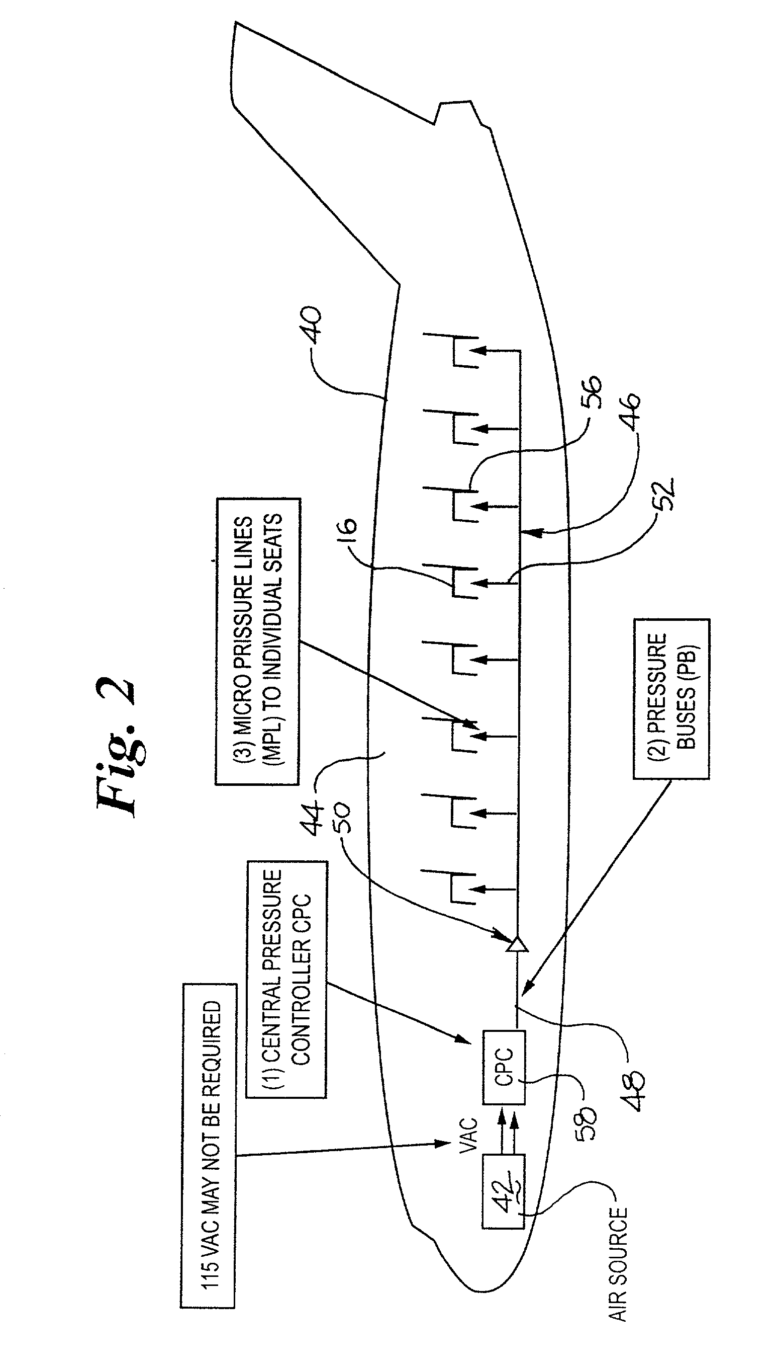
[0035] FIG. 2 is a side view of an embodiment of the invention wherein the inventive system is utilized on an airplane.

[0036] FIG. 3 is a schematic depiction of an embodiment of a controller utilized in at least one embodiment of the inventive system.

[0037] FIG. 4 is a frontal view of an embodiment of an inflatable sleeve which is a cuff that may be utilized in at least one embodiment of the inventive system.

[0038] FIG. 5 is a close-up side view of an embodiment of an inflation member and plug utilized with the inflatable sleeve depicted in FIG. 4.

[0039] FIG. 6 is a frontal view of an embodiment of an embodiment of the invention wherein inflatable sleeve is a cuff.

[0040] FIG. 7 is a schematic view of a valve assembly configuration which may be utilized in an embodiment ...


PUM


Abstract

A system for providing prophylaxis against thrombosis comprises in combination a vehicle and a plurality of inflatable compression sleeves. The vehicle has a pneumatic pressure source for supplying a predetermined flow of pneumatic fluid to a plurality of passenger positions. The pneumatic pressure source has a plurality of leads, which extend to a connection port located in each of the passenger positions. Each of the inflatable compression sleeves has a plurality of inflatable chambers therein. The sleeves are constructed to be engaged to a connection port, thereby providing fluid communication between the pneumatic pressure source and the plurality of chambers. The sleeves may be worn by a passenger to help prevent the occurrence of deep vein thrombosis. Individual sleeves comprise at least two inflatable chambers wherein a second inflatable chamber is subsequent to the inflation of a first inflatable chamber.

Description

[0001] This application claims priority from U.S. provisional application No. 60 / 262,048, filed Jan. 16, 2001, the entire content of which is incorporated herein by reference.[0002] Not Applicable[0003] 1. Field of the Invention[0004] The present invention is directed to several embodiments. In at least one embodiment the invention is directed to an apparatus for improving the vascular blood flow in the extremities of individuals who are positioned in a confined manner, such as for example those traveling for long distances in an airplane or other vehicle. In at least one embodiment, the invention is directed to a system having at least one rhythmically inflatable cuff, sleeve, collar or other member that may be fitted around one or more limbs, particularly the leg or legs, of one or more individuals that is pneumatically activated encouraging blood flow and preventing deep vein thrombosis from occurring in the limb or limbs of any individual wearing the rhythmically inflatable memb...

Claims


Application Information

Patent Timeline
Patent Type & Authority Applications(United States)
IPC IPC(8): A61H23/04B64D10/00B64D11/06
CPCA61H9/0078B64D10/00B64D11/06B64D2010/002Y02T50/46B64D11/0607Y02T50/40
Inventor KUSLICH, STEPHEN D.PETERSON, FRANCIS
Owner KUSLICH STEPHEN D
Why Eureka
Try Eureka