Motor control apparatus and electric vehicle using same

a technology of motor control apparatus and electric motor, which is applied in the direction of electronic commutators, motor/generator/converter stoppers, dynamo-electric converter control, etc., can solve problems such as complicated operations and out-of-synchronization of control apparatus

Inactive Publication Date: 2002-08-29
HITACHI LTD
View PDF1 Cites 45 Cited by
  • Summary
  • Abstract
  • Description
  • Claims
  • Application Information

AI Technical Summary

Problems solved by technology

Since a synchronous motor control apparatus based on the magnetic pole position sensor-less control system eliminates a position detector, the control apparatus could experience a problem of out-of-synchronism due to erroneous detection of magnetic pole position.
However, the system described in JP-A-9-294390 requires complicated operations involved in calculating a square root for finding the effective current value of the stator winding of the motor and in calculating the power factor angle.

Method used


Image

  • Motor control apparatus and electric vehicle using same
  • Motor control apparatus and electric vehicle using same
  • Motor control apparatus and electric vehicle using same

Examples


first embodiment

[0042] To begin with, the configuration and operation of a synchronous motor control apparatus according to the present invention will be described with reference to FIGS. 1 through 5.

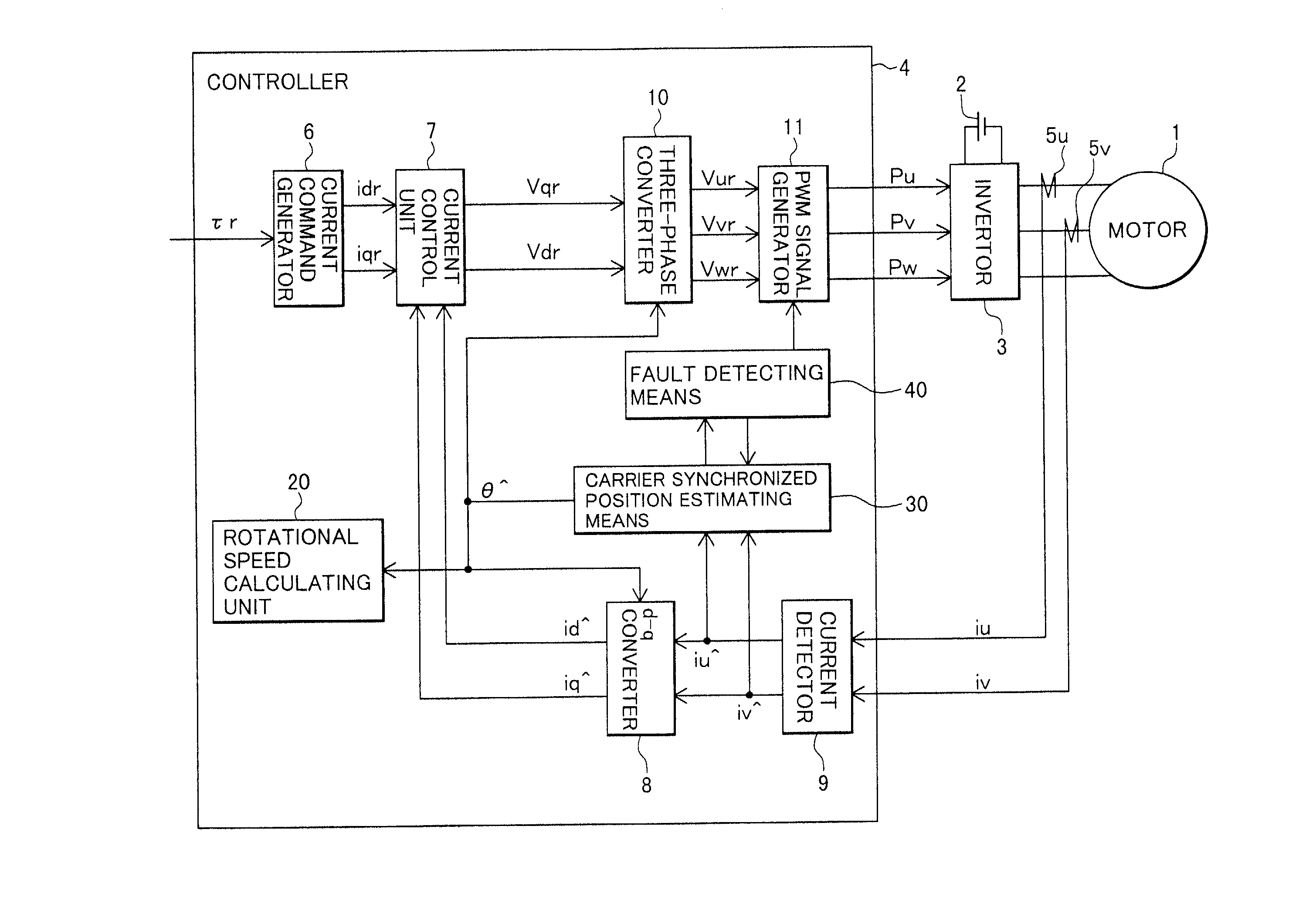
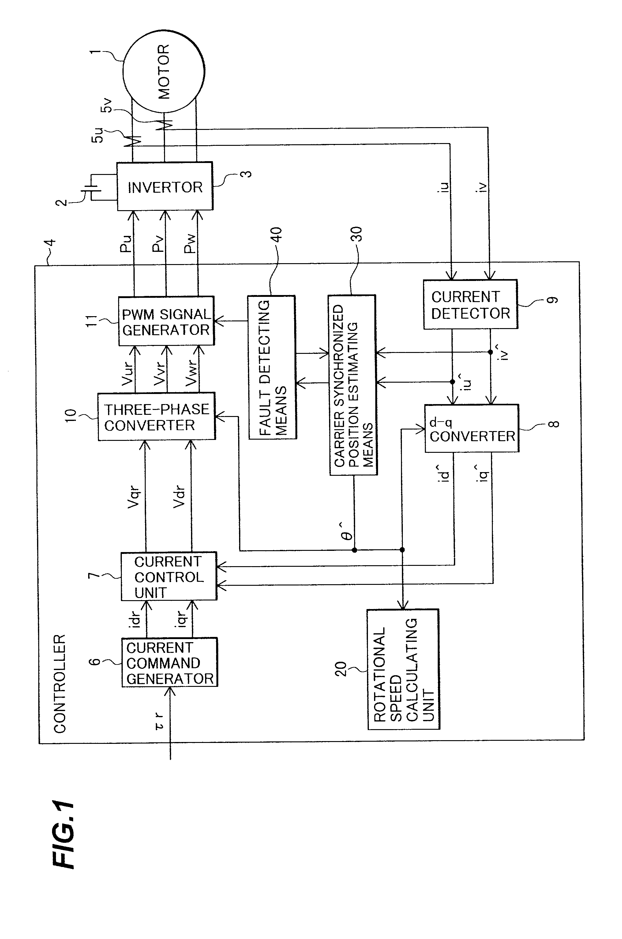
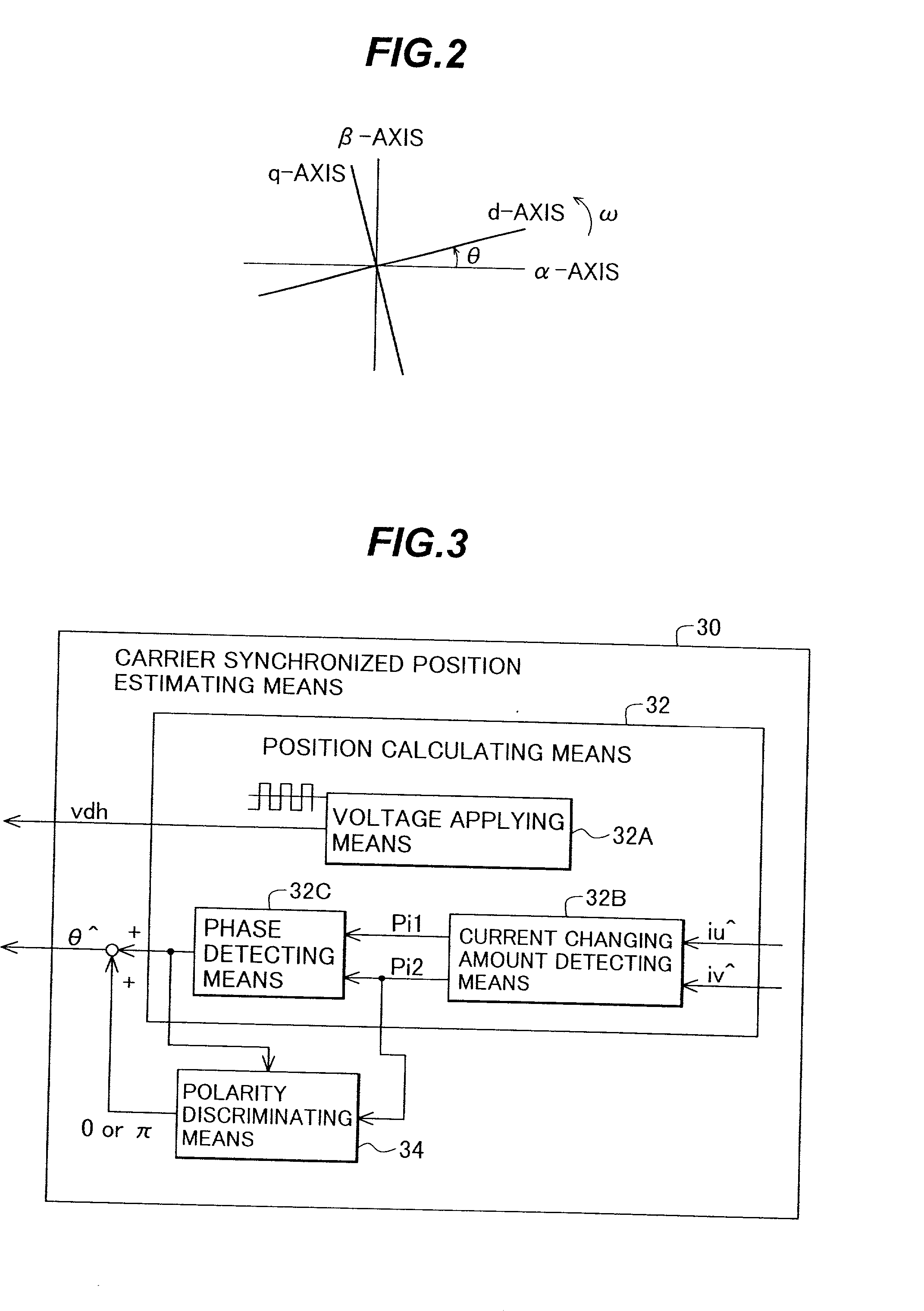
[0043] FIG. 1 is a block diagram illustrating the configuration of the synchronous motor control apparatus according to the first embodiment of the present invention, and FIG. 2 is an explanatory diagram of a rotating coordinate system for use in the synchronous motor control apparatus of FIG. 1.

[0044] A direct current (DC) voltage from a battery 2 is converted to three-phase AC voltages by an invertor 3, and applied to an AC synchronous motor 1. The applied voltage is calculated and determined by a controller 4.

[0045] The controller 4 comprises a current command generator 6, a current control unit 7, a d-q converter 8, a current detector 9, a three-phase converter 10, a PWM signal generator 11, a rotational speed calculating unit 20, a carrier type magnetic pole position estimating means 30, and a fau...

second embodiment

[0075] Next, the configuration and operation of a synchronous motor control apparatus according to the present invention will be described with reference to FIGS. 6 and 7.

[0076] FIG. 6 is a block diagram illustrating the configuration of the synchronous motor control apparatus according to the second embodiment of the present invention, where the same reference numerals as those in FIG. 1 designate the same components.

[0077] A fault detecting means 40 comprises an instantaneous power calculating unit 41, an operation mode processing unit 42, and a phase inversion determining unit 43. The magnetic pole position can be estimated by the magnetic pole position estimating means 30 over a limited range of 180-, so that if an estimated magnetic pole position has been inverted by some cause by 180-, the inversion of the position is detected by a fault detecting means 40.

[0078] The instantaneous power calculating unit 41 calculates the output instantaneous power of the motor by the following...

third embodiment

[0085] Next, the configuration and operation of a synchronous motor control apparatus according to the present invention will be described with reference to FIG. 8.

[0086] FIG. 8 is a block diagram illustrating the configuration of the synchronous motor control apparatus according to the third embodiment of the present invention, where the same reference numerals as those in FIGS. 1, 6 designate the same components.

[0087] In the third embodiment, a fault detector 40A comprises an input power calculating unit 44 instead of the instantaneous power calculating unit 41 illustrated in FIG. 6. The input power calculating unit 14 calculates input power from a product of a DC voltage VB of a battery 2 detected by a resistor 25 and a DC current IB detected by a current sensor 26. A phase inversion determining unit 43 relies on the input / output relationship between an operation mode determined by the operation mode processing unit 42 and the input power calculated by the input power calculatin...


PUM


Abstract

A synchronous motor controlling apparatus which can be applied to the carrier synchronized position estimating method as well and have protection-related functions such as detection of inverted magnetic pole position of a motor in a simple method, and an electric motor using the synchronous motor control apparatus. A controller controls a voltage applied to an AC motor with a PWM signal. A magnetic pole position detector of the controller detects a current of the AC motor to estimate a pole position of the AC motor. A fault detector detects a fault in the estimated magnetic position of the AC motor.

Description

[0001] 1. Field of the Invention[0002] The present invention relates to a motor control apparatus and an electric motor using the same, and more particularly, to a motor control apparatus and an electric motor using the same which are suitable for use in a magnetic pole position estimation system for estimating a magnetic pole position of an alternating current (AC) synchronous motor.[0003] 2. Description of the Related Art[0004] Generally, since the phase of an AC voltage applied to a synchronous motor is determined by a current magnetic pole position of a rotor, exact pole positions of the rotor are required for controlling the synchronous motor. A torque and speed of the synchronous motor can be controlled by conducting a current control or a voltage control based on the detected magnetic pole position. In recent years, a magnetic pole position sensor-less control system has been proposed for controlling a synchronous motor without using a position detector for detecting the magn...

Claims


Application Information

Patent Timeline
Patent Type & Authority Applications(United States)
IPC IPC(8): B60L15/20H02P3/18H02P6/06H02P6/08H02P6/18H02P6/182H02P6/28H02P21/00H02P21/05H02P21/14H02P21/18H02P21/22H02P21/24H02P21/28H02P21/34H02P23/04H02P23/14H02P25/026H02P27/04H02P27/08
CPCB60L11/1803B60L15/025B60L2220/14H02P3/18H02P6/16H02P21/0035H02P21/04Y02T10/643Y02T10/7005Y02T10/7258B60L50/51H02P21/22Y02T10/64Y02T10/70Y02T10/72
Inventor SAWADA, TAKEFUMIKANEKO, SATORUMASAKI, RYOSOHOMBU, MITSUYUKIKATAYAMA, HIROSHI
Owner HITACHI LTD
Why Eureka
Try Eureka