[0006] The chainsaw according to the invention, with the features of claim 1, has the
advantage that a position of the blade in relation to the sprocket selected by the chainsaw user can be secured in a form-fitting fashion and only has to be readjusted if the chain has lengthened as a result of wear or if the blade and the sprocket and / or the deflection wheel have been worn down. Here, the chain tensioning device can be operated manually without any tools. For this purpose, it is merely necessary to alternately rotate two handwheels that are disposed concentrically and immediately adjacent to one another, each in the same direction. An automatic slackening of the chain pre-stressing device with the result of decreasing chain tension during operation of the chainsaw is reliably prevented by ability to the positionally lock the cam disc in a form-fitting fashion by means of the handwheels because the blade is thus held fixed in the set tension position.
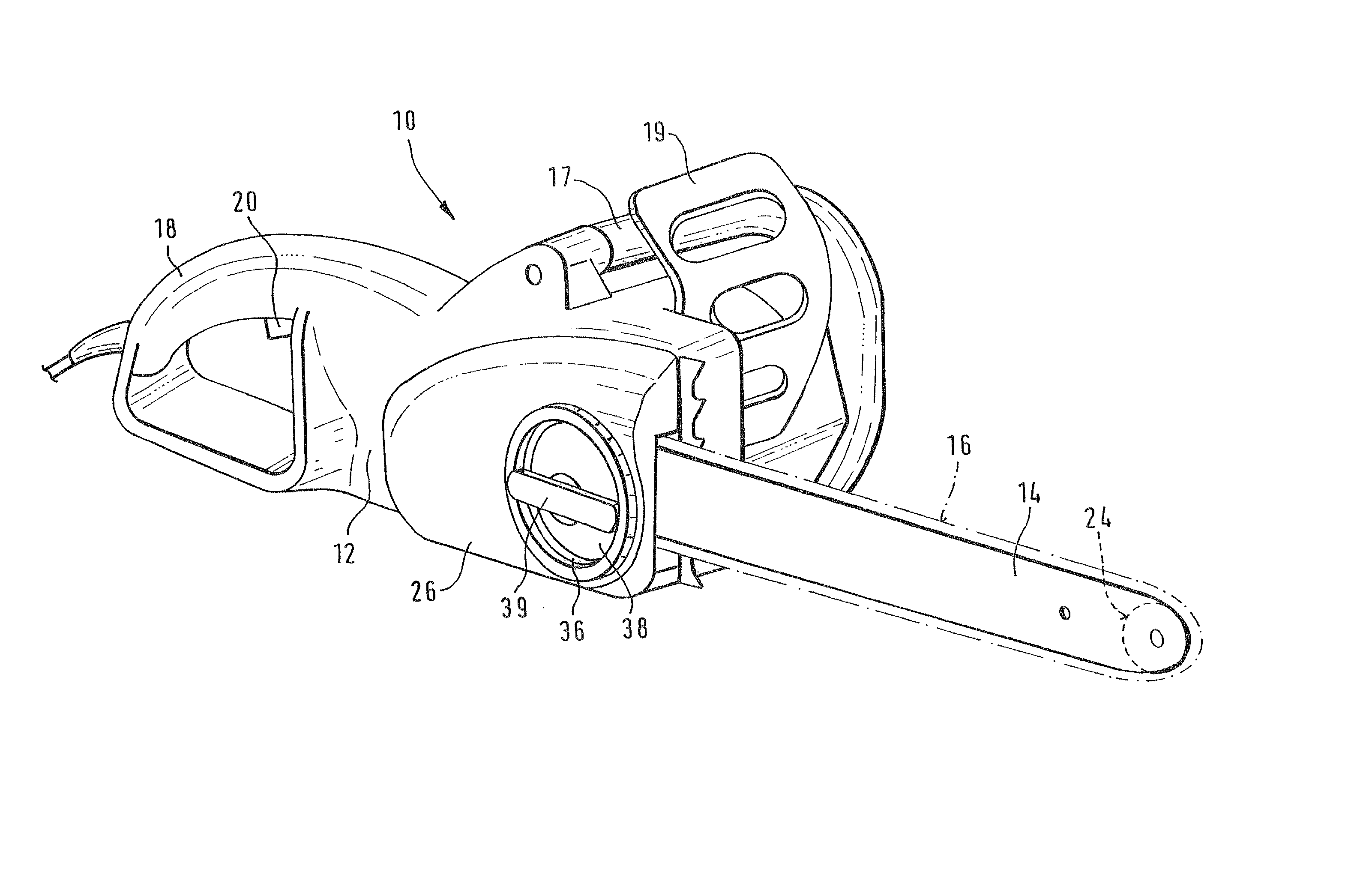
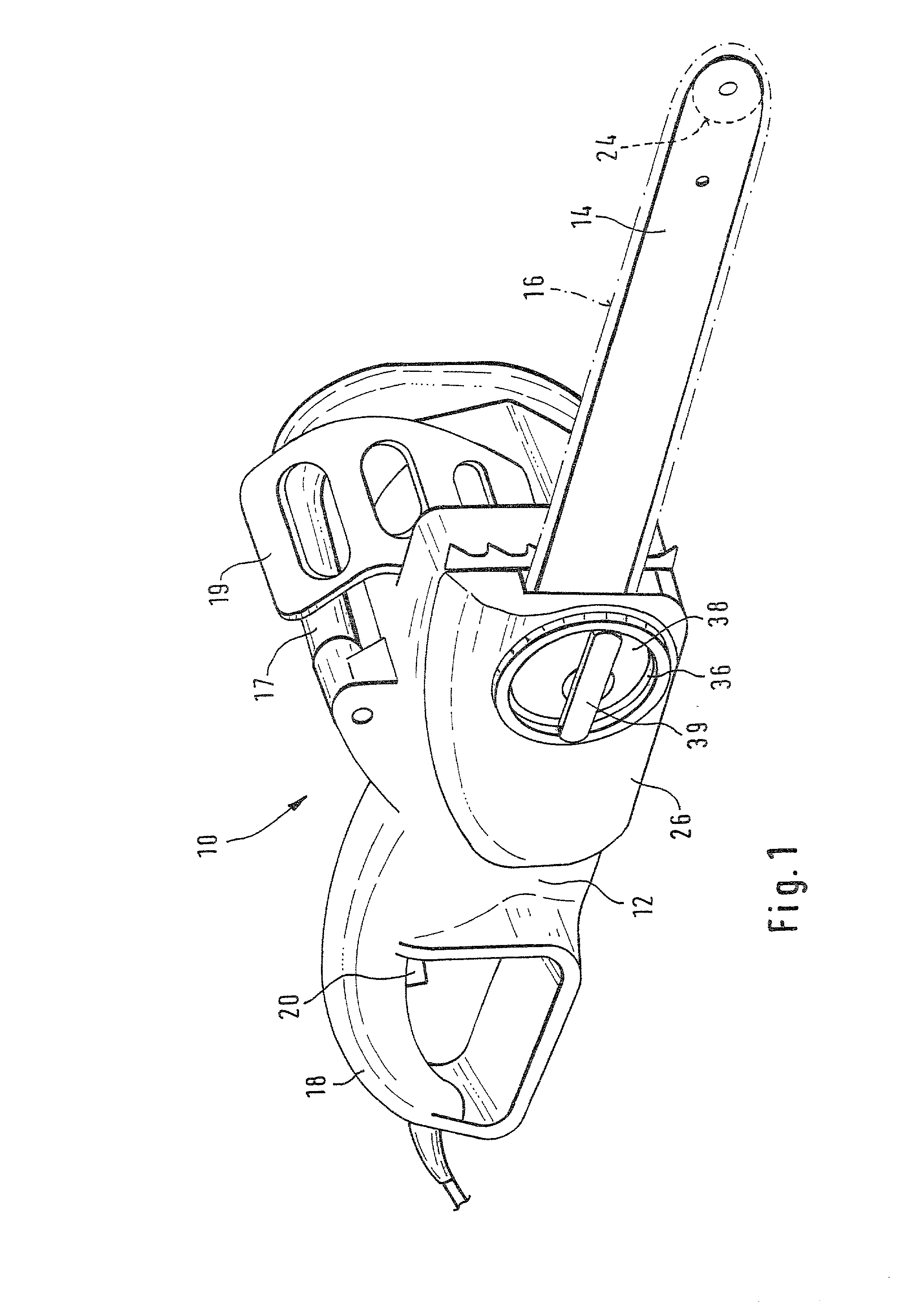
[0007] By virtue of the fact that the rotational member is comprised of two shell-like handwheels that can be slid one into the other and rotated in relation to one another around a common axis, a convenient operation is produced with which the saw chain can be tensed without tools using one hand, in a "blind" fashion, i.e. without the user having to search for the control elements.
[0012] By virtue of the fact that the
detent coupling is preferably embodied as a radial
detent coupling, the rotational position of the outer handwheel can be locked with the greatest possible locking action. In this instance, this locking position can be established in a form-fitting fashion by means of the inner handwheel in such a way that it cannot be changed unintentionally during operation of the chainsaw.
[0009] By virtue of the fact that the outer handwheel is coupled to the cam in a rotation-transmitting manner, in particular by way of an internal spline / external spline connection, a
secure transmission of rotation to the cam is assured, with the connection between the outer handwheel and the cam being particularly simple to produce and assemble, due to the fact that it can have coarse tolerances.
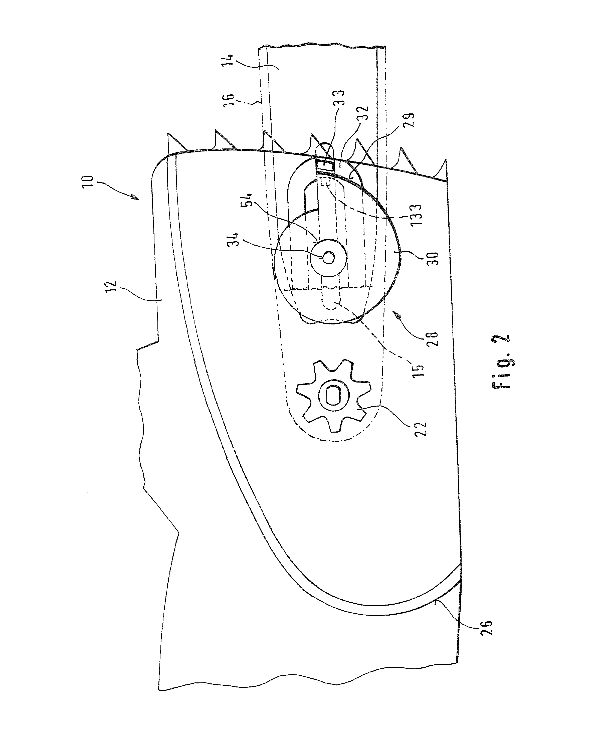
[0010] By virtue of the fact that the cam is mounted so that it can be moved axially and elastically in relation to the housing and / or the handwheel, after the cam has been rotated a maximum of three-quarters of a rotation, it locks into its working position in relation to a stop plate drive-connected to the blade. In this manner, the
assembly of the chain tensioning device is simple and safe from
user error, e.g., after the saw chain has been changed.
[0011] By virtue of the fact that the outer handwheel can, by way of a
detent coupling, be coupled to the housing, in particular to the sprocket cover, an undesired change in the saw chain tension during the adjustment process is prevented.
[0012] By virtue of the fact that the detent coupling is preferably embodied as a radial detent coupling, the rotational position of the outer handwheel can be locked with the greatest possible locking action. In this instance, this locking position can be established in a form-fitting fashion by means of the inner handwheel in such a way that it cannot be changed unintentionally during operation of the chainsaw.
[0013] By virtue of the fact that the inner handwheel can be coupled to the outer handwheel in a detachable fashion by way of an axial detent coupling, the inner handwheel can also be secured in a non-rotational fashion, thus preventing the unintentional release of the axial locking of the blade as well as of the chain tensioning device.
[0013] By virtue of the fact that the inner handwheel can be coupled to the outer handwheel in a detachable fashion by way of an axial detent coupling, the inner handwheel can also be secured in a non-rotational fashion, thus preventing the unintentional release of the axial locking of the blade as well as of the chain tensioning device.
[0007] By virtue of the fact that the rotational member is comprised of two shell-like handwheels that can be slid one into the other and rotated in relation to one another around a common axis, a convenient operation is produced with which the saw chain can be tensed without tools using one hand, in a "blind" fashion, i.e. without the user having to search for the control elements.
[0016] By virtue of the fact that an inner protective cover closes the chain tensioning device from the inside at the sprocket cover, dust and shavings are prevented from penetrating into the chain tensioning device and thus impairing its function.
[0017] By virtue of the fact that the chain tensioning device has an elongated, angular stop plate for gripping the cam, which can be fixed to the blade, the stop plate is particularly resistant to deformation and bending while using a particularly small amount of material, so that the chainsaw is lighter and the chain tensioning device operates in a more directly responsive manner than is the case with known U-shaped stop plates.

