Input device with capacitive antenna

a capacitive antenna and input device technology, applied in the field of input devices, can solve the problems of requiring a very small amount of power, requiring a rather power-hungry task, and a less effective approach, and achieve the effect of minimizing the capacitance of the antenna of the user's hand and saving power

Inactive Publication Date: 2002-09-12
LOGITECH EURO SA
View PDF3 Cites 46 Cited by
  • Summary
  • Abstract
  • Description
  • Claims
  • Application Information

AI Technical Summary

Benefits of technology

0013] In one embodiment, the antenna is a capacitive antenna. A capacitor is switched in parallel with the antenna when it is used in antenna mode, so that the impact on the antenna signaling of the capacitance of a user's hand is minimized.
0014] In one embodiment, a sleep mode is provided for the electronic circuitry to conserve power. The hand detect signal will awaken the input device from its sleep mode.

Problems solved by technology

When the device is idle, the wake-up circuitry is active but requires a very small amount of power.
In a mouse, activity monitoring requires flashing the encoder Light Emitting Diodes (LEDs) and reading back the photodetector signals in order to detect a potential horizontal movement, a rather power hungry task.
This approach is less effective than the former since monitoring typically requires more power than that required in the microcontroller idle state.
While the two approaches have proven to be very effective, both suffer from their own limitations.
The interrupt approach limitation is the fact that a pointing device must be "wakened up" by clicking on a switch when in power saving mode, e.g. there is no automatic waking up when the user moves the pointing device as is currently the case in Logitech products.
On the other hand, the monitoring approach doesn't require a clicking wake up action, but suffers from a rather long latency time when the device is in this monitoring mode, the shortening the latency time being in contradiction with the power saving objectives.
The problem of power consumption is particularly troublesome in the new mice using an optical module, which detects the reflection of light off a surface to determine mouse movement.
When such a device is made wireless, requiring a transmitter (e.g., radio or infrared) as well, it is difficult to have the batteries last more than a couple of months.

Method used


Image

  • Input device with capacitive antenna
  • Input device with capacitive antenna
  • Input device with capacitive antenna

Examples


Embodiment Construction

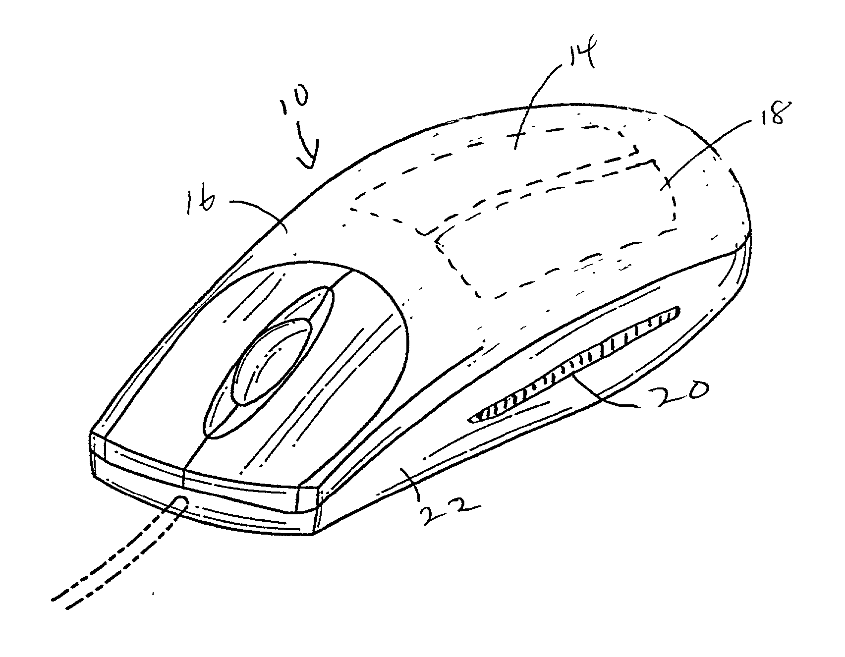
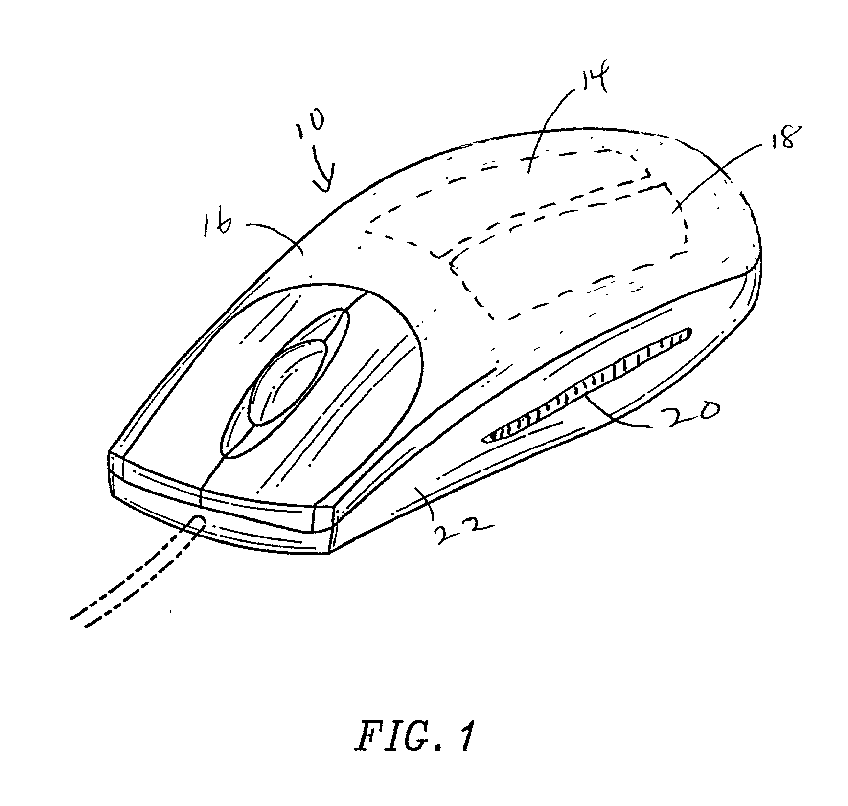
[0023] FIG. 1 illustrates a mouse 10 having a top housing cover 16 beneath which, in phantom, are shown sheet electrodes 14 and 18. Additionally, an exposed electrode 20 is shown on a side 22 of the mouse. A similar electrode can be mounted on the other side, not shown. The electrodes 14, 18, or / and 20, are connected to a capacitive detection circuit for detecting when a hand is touching or in close proximity to those electrodes.

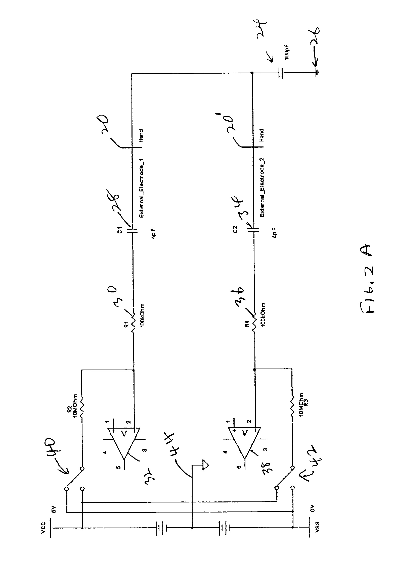
[0024] FIG. 2A illustrates, at a high level, the operation of the capacitive detection circuit. FIG. 2A illustrates a direct connection from the hand to the detection circuit, such as through exposed electrode 20 and a corresponding second electrode 20'. When the hand touches these, the capacitance of the body 24 to an earth ground 26 is connected in series with the electrodes. As shown, first electrode 20 is connected through a capacitor 28 and a resistor 30 to one input of a comparator 32. Similarly, the second electrode 20'is connected through a capacitor...


PUM


Abstract

An input device having a housing and electronic circuitry for detecting user inputs, and transmitting signals corresponding to those inputs to an electronic device, such as a computer. An antenna is provided for transmitting or receiving signals. A hand detection circuit is provided, which uses said antenna for detecting the proximity of a user's hand to the housing and producing a hand detect signal in response. In one embodiment, the antenna is a capacitive antenna. A capacitor is switched in parallel with the antenna when it is used in antenna mode, so that the impact on the antenna signaling of the capacitance of a user's hand is minimized. In one embodiment, a sleep mode is provided for the electronic circuitry to conserve power. The hand detect signal will awaken the input device from its sleep mode.

Description

CROSS-REFERENCES TO RELATED APPLICATIONS[0001] This application is a Continuation-in-part of U.S. application Ser. No. 09 / 964,975, filed Sep. 26, 2001, entitled "Input Device With Hand Detection" , which is a non-provisional of U.S. application Ser. No. 60 / 261,543, filed Jan. 12, 2001, which disclosures are incorporated herein by reference.STATEMENT AS TO RIGHTS TO INVENTIONS MADE UNDER FEDERALLY SPONSORED RESEARCH OR DEVELOPMENT NOT APPLICABLEREFERENCE TO A "SEQUENCE LISTING," A TABLE, OR A COMPUTER PROGRAM LISTING APPENDIX SUBMITTED ON A COMPACT DISK NOT APPLICABLEBACKGROUND OF THE INVENTION[0002] The present invention relates to input devices, in particular pointing devices such as mice, and more particularly to antennas for such devices.[0003] Wireless mice, trackballs and other devices use batteries and an antenna to transmit to a receiving unit connected to a computer. Different types of antennas could be used, such as a capacitive or an inductive antenna. One concern especial...

Claims


Application Information

Patent Timeline
Patent Type & Authority Applications(United States)
IPC IPC(8): G06F1/32G06F3/038
CPCG06F1/3203G06F1/3231G06F1/3259Y02D10/173G06F3/0383H03K2217/960775Y02D10/155G06F3/03543Y02D10/00
Inventor JUNOD, PHILIPPEKEHLSTADT, FLORIAN MAX
Owner LOGITECH EURO SA
Why Eureka
Try Eureka