
Spectrum division multiplexing for high channel count optical networks

a technology of optical networks and spectrum division, applied in the field of optical communication, can solve the problems of many filtering components and modules, adding and/or dropping a group of signal channels,

Inactive Publication Date: 2002-09-12
NEXFON CORP
View PDF16 Cites 32 Cited by
  • Summary
  • Abstract
  • Description
  • Claims
  • Application Information

AI Technical Summary

Problems solved by technology

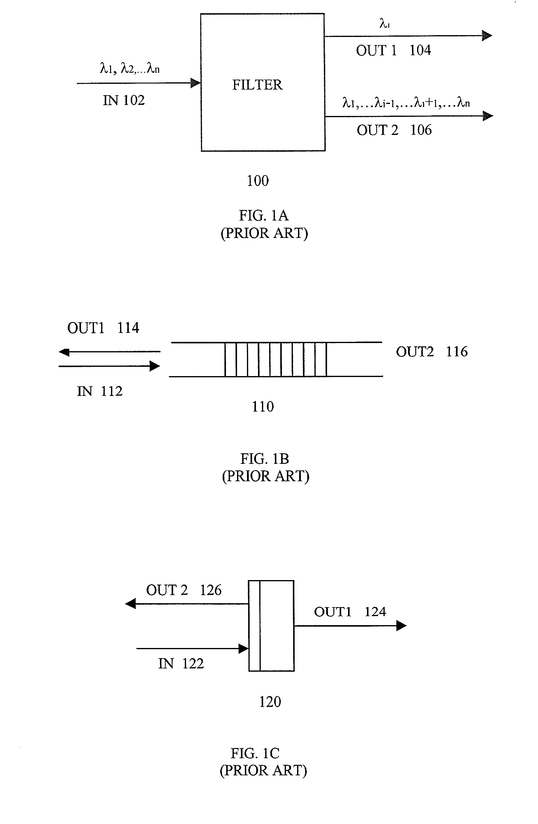
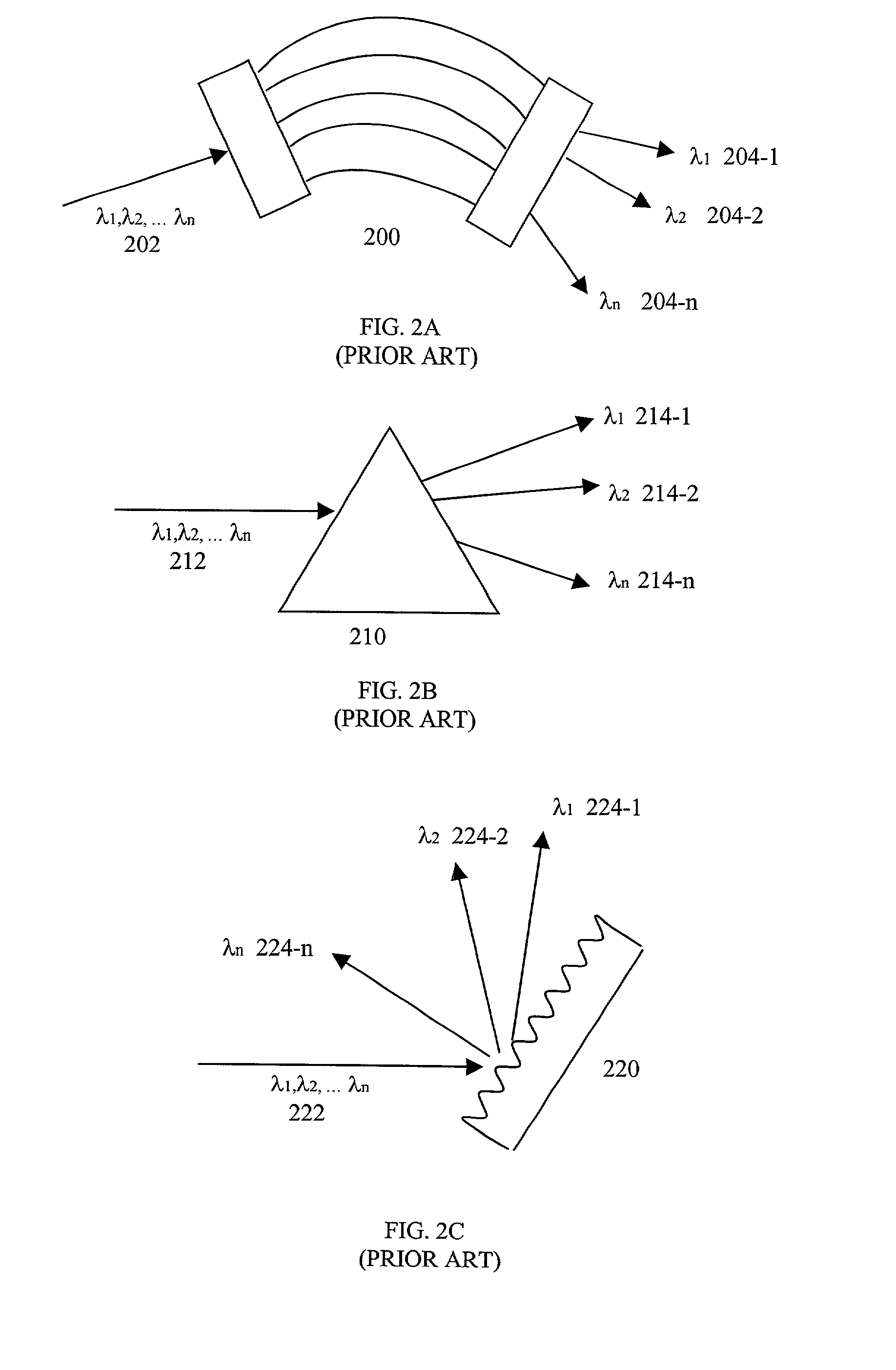
One problem with wavelength filters is that several of them ordinarily must be cascaded together in order to separate a composite optical signal (one including multiple information modulated wavelengths) into its constituent wavelengths.
One of the disadvantages of interleavers employing earlier add / drop modules is that adding and / or dropping a group of signal channels often involves many filtering components and modules.

Method used


Image

  • Spectrum division multiplexing for high channel count optical networks
  • Spectrum division multiplexing for high channel count optical networks
  • Spectrum division multiplexing for high channel count optical networks

Examples


embodiment 1000

[0089] In a present interleaver embodiment 1000, the ring resonators 1012, 1014 provide a periodic wavelength-dependent phase shift that can be expressed in accordance with the following equation. 1 = arctan ( r 2 - 1 ) sin 2 r - ( 1 + r 2 ) cos ( 1 )

[0090] with 2 = 2 L 0 ( 2 )

[0091] and

r.sup.2=R (3)

[0092] where L.sub.0 is the optical path length of the ring, .lambda. is the wavelength of the light in air, and R is the coupling coefficient of the coupler between one respective arm 1008 or 1010 of the Mach-Zhender 1002 and a corresponding respective ring resonator 1012, 1014. The phase shift imparted by a respective ring resonator can be adjusted by changing L.sub.0.

[0093] The sharpness of the filter effect of the interleaver 1000, i.e., the slopes of the transmission curve on two sides of a pass band can be determined by the reflectivity of the respective ring resonators 1012, 1014. The quality of the OSS 1000, as measured in terms of closeness of the first and second output beam sp...

embodiment 1100

[0113] Referring now to the illustrative drawing of FIG. 14, there is shown a generalized block diagram of a spectrum exchanger 1400 which may be implemented in accordance with the invention. In operation, an input optical signal IN 1 with a first wavelength spectrum is provided to input 1402, and an input optical signal IN 2 with a second wavelength spectrum is provided to input 1404. The spectrum exchanger 1400 provides an output optical signal OUT 1 that that has the first wavelength to output 1406. The spectrum exchanger 1400 provides an output optical signal that has the second wavelength spectrum to output 1408. The spectrum exchanger 1400 may be constructed using any of the embodiments described with reference to FIGS. 9A-13, for example. For instance, assuming that FIG. 11 is used to implement the spectrum exchanger 1400, the first, second and third phase shifts imparted by such interleaver 1100 would be selected such that the input optical signal 1120 would be provided as t...


PUM


Abstract

An optical interleaver comprising: an interferometer which includes a coupler, a first phase shifter and a combiner; wherein the coupler splits incident light into a first light beam and a second light beam and couples the first light beam and the second light beam to the first phase shifter; wherein the first phase shifter includes a first light propagation element that propagates the first light beam along a first path between the coupler and the combiner and that includes a second light propagation element that propagates the second light beam along a second path between the coupler and the combiner, the first and second paths having different path lengths that contribute to a phase shift between light of the first light beam propagated along the first path and light of the second light beam propagated along the second path; wherein the combiner couples the first light beam with and the second light beam; a second phase shifter which receives first light beam light propagated along the first path between the coupler and the combiner and imparts a first wavelength dependent variation in phase to the received first light beam light; a third phase shifter which receives second light beam light propagated along the second path between the coupler and the combiner and imparts a second wavelength dependent variation in phase to the received second light beam light.

Description

CROSS REFERENCE TO RELATED APPLICATIONS[0001] This application is a continuation-in-part of commonly assigned pending application Ser. No. 09 / 738,904 filed Dec. 16, 2000.BACKGROUND OF THE INVENTION[0002] 1. Field of the Invention[0003] The present invention relates generally to the field of optical communications and more particularly to wavelength / spectrum interleaving in dense wavelength division multiplexing (DWDM) applications.[0004] 2. Description of the Related Art[0005] Optical communications is an active area of new technology and is crucial to the development and progress of several important technologies, e.g., Internet and related new technologies. A key technology that enables higher data transmission rate is dense wavelength division multiplexing (DWDM). In the DWDM technology, optical signals (Information modulated light at prescribed wavelengths) generated from different sources operating at predetermined, densely spaced center wavelengths, are combined (or multiplexe...

Claims


Application Information

Patent Timeline
IPC IPC(8): H04J14/02
CPCH04J14/02
Inventor QIAN, CHARLES X. W.LI, YIFANQIN, YISU, ZHENPENG
Owner NEXFON CORP
Learn More