
Packet transmission method and system, and packet transmitting apparatus, packet receiving apparatus, and packet transmitting/receiving apparatus

a packet transmission and packet technology, applied in the field of packet transmission methods and systems, can solve the problems of large delay, affecting the transmission of real-time type packets requiring minimal delay, and allowing some delay

Active Publication Date: 2002-09-12
NTT DOCOMO INC
View PDF9 Cites 170 Cited by
  • Summary
  • Abstract
  • Description
  • Claims
  • Application Information

AI Technical Summary

Benefits of technology

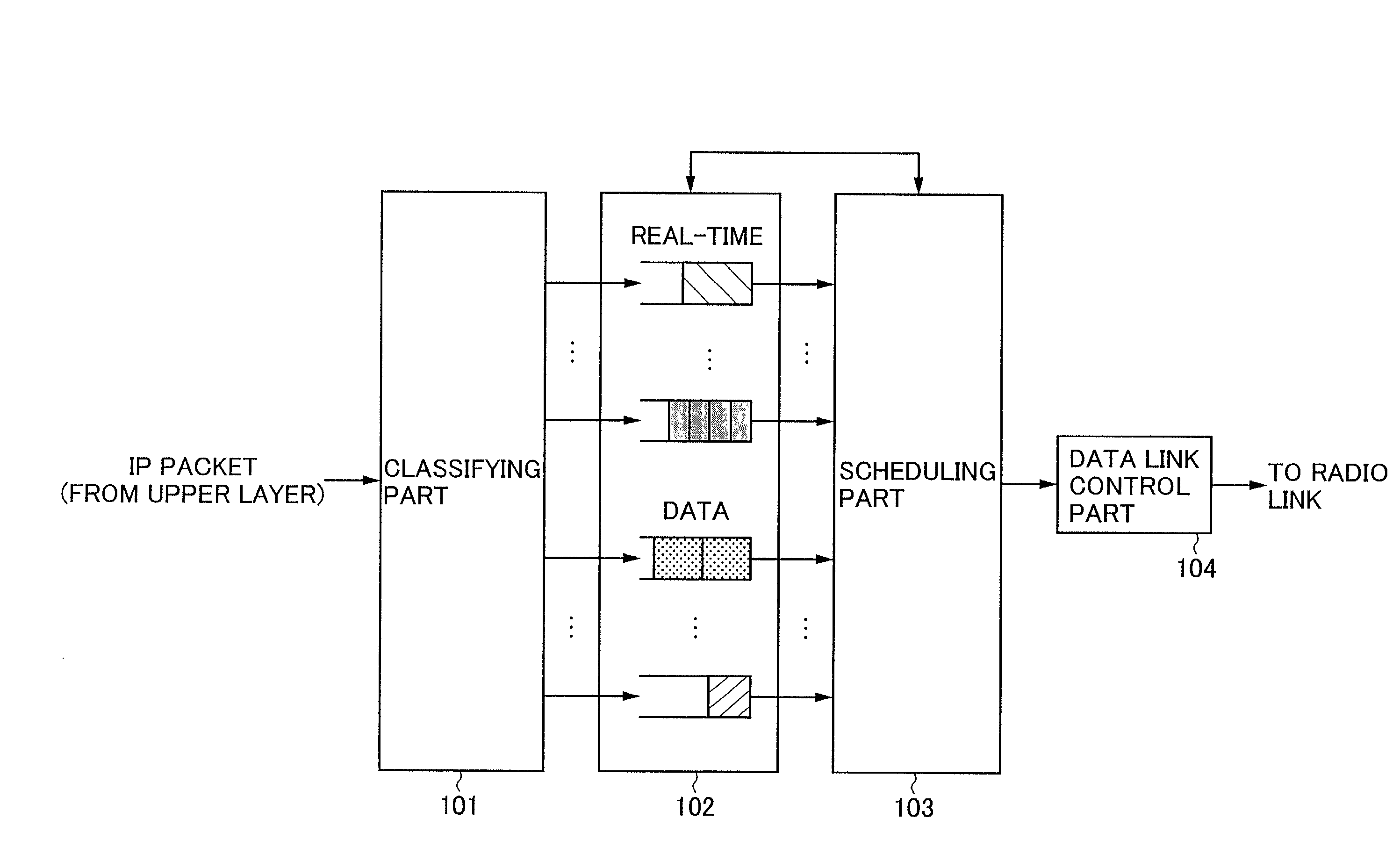
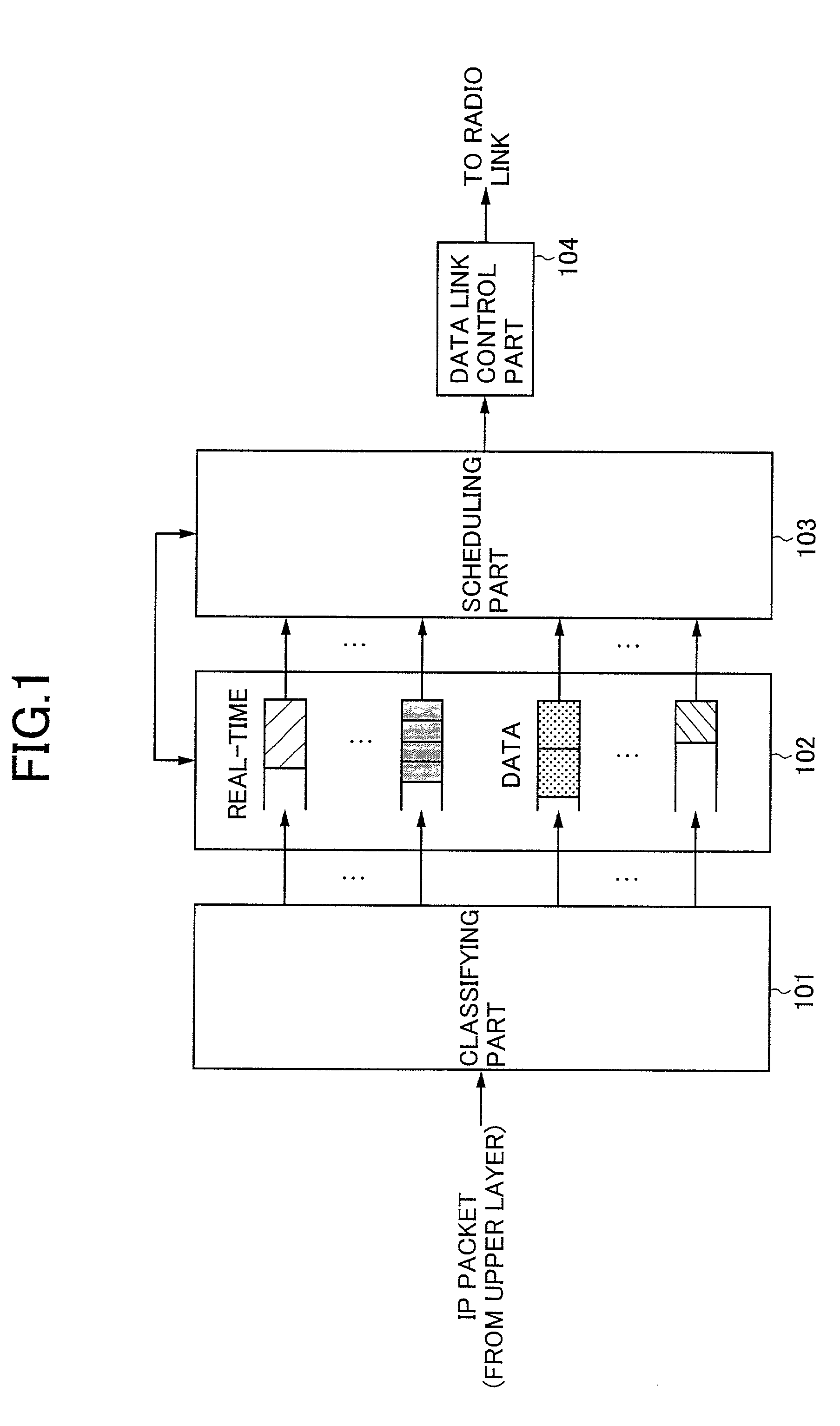
[0030] The present invention is directed toward solving these problems, and hence its object is to provide the packet transmission method and system that performs the data link control taking into account the QoS in order to achieve minimal delay of the real-time type packets in the radio transmission, while maintaining the reliability of the data type packets.
[0036] It may be possible to add a header compression process to one of the above aspects to reduce the amount of the transmitted information.

Problems solved by technology

That is, the data type transmission may allow some delay if necessary for the reliability.
While, in real-time type transmission such as for audio or video streaming, minimal delay is more important because the real-time type data can be practically unusable if the delay is too large.
If such QoS control method is applied to radio transmission where packet losses may likely occur in radio paths, a larger delay may adversely occur in the real-time type packets requiring minimal delay.
Therefore, applying the above conventional QoS control to the radio transmission, the transmission delay may likely occur in the transmission of the real-time type packets where minimal delay may be more important than the reliability.
Thus, in the conventional data link control apparatus, the QoS control is exclusively performed in the IP layer (the third layer), and the QoS is not adequately reflected in the process of the data link layer (the second layer).
Therefore, the conventional packet transmitting apparatus has a problem that the transmission delay is likely to occur in the real-time type packets when it is used for the radio transmission.
However, although this method varies its retransmission method on the basis of the QoS requirement, the above-mentioned problem that the delay may occur in the real-time type packets due to the occurrence of the retransmission packet waiting time remains, because this method does not include a mode that does not perform the retransmission method.
Also, in this method, although a frame length to divide into is varied in the data link layer according to conditions of the radio transmission path, a frame by frame scheduling is not performed.
Therefore, this method does not solve the problem that delay may occur in the real-time type packets because of the transmission waiting time until completion of transmission of the data type packets.

Method used


Image

  • Packet transmission method and system, and packet transmitting apparatus, packet receiving apparatus, and packet transmitting/receiving apparatus
  • Packet transmission method and system, and packet transmitting apparatus, packet receiving apparatus, and packet transmitting/receiving apparatus
  • Packet transmission method and system, and packet transmitting apparatus, packet receiving apparatus, and packet transmitting/receiving apparatus

Examples


first embodiment

[0057] First, the packet transmitting system according to the present invention is described with reference to FIGS. 3-5. FIG. 3 shows the configuration of the packet transmitting apparatus according to this embodiment, FIG. 4 shows the configuration of the packet receiving apparatus according to this embodiment, and FIG. 5 shows the configuration of the packet transmitting / receiving apparatus according to this embodiment.

[0058] As shown in FIG. 3, the packet transmitting apparatus according to this embodiment includes a classifying part 301, an IP queue 302, a data link control part 303, and a scheduling part 306. The data link control part 303 includes dividing parts 304 and retransmission control parts 305.

[0059] The classifying part 301 classifies the IP packets input from an upper layer into different IP datagram queues on the basis of the QoS requirement obtained from, for example, IP header information of the packets.

[0060] The IP queue 302 includes a plurality of IP datagram...

third embodiment

[0101] The packet transmission method and system according to the present invention is now described with reference to FIGS. 13-16.

[0102] A header in the packet transmission has high compressibility, because the information included in the header may hold the same contents in some cases, and the subsequent value may be easily predicted. In the prior art, it is proposed to compress the header of each packet in the packet transmission in order to reduce an amount of transmitted information. This embodiment applies the header compressing process to the packet transmission system according to the present invention.

[0103] FIG. 13 shows the configuration of the packet transmitting apparatus according to this embodiment, FIG. 14 shows the configuration of the packet receiving apparatus according to this embodiment, FIG. 15 shows the process of the data unit transmission in the packet transmitting apparatus according to this embodiment, and FIG. 16 shows the process of the data unit recepti...

fourth embodiment

[0117] The packet transmission method and system according to the present invention is now described with reference to FIG. 17. FIG. 17 shows the configuration of the packet transmitting apparatus according to this embodiment.

[0118] In FIG. 17, the pre-scheduling part 1701 processes each of the packets to be transmitted packet by packet on the basis of the QoS requirement, as with the conventional scheduling part such as the scheduling part 103 shown in FIG. 1.

[0119] The classifying part 1702 classifies the IP packets by outputting each of the pre-scheduled IP packets to different dividing parts 304 on the basis of the QoS requirement obtained from, for example, the IP header information of the IP packets, as with the classifying part 301 according to the first embodiment of the present invention (see FIG. 3).

[0120] Now, along the process flow, a section from the classifying part 301 to the pre-scheduling part 1701 is referred to as a first half section, and a section from the class...


PUM


Abstract

A packet transmission method for transmitting packets classified according to a quality of service (QoS) requirement from a transmitting node to a receiving node is provided. In the transmitting node, the steps of: selecting sequentially a QoS class; dividing a queued packet to be transmitted belonging to the selected class into a plurality of predetermined data units, and transmitting one of the obtained predetermined data units; and applying a transmitter-side retransmission control process to the data unit to be transmitted when the selected class is a QoS class specified for data type packets are provided. In the receiving node, the steps of: receiving sequentially the data units transmitted from the transmitting node; assembling a plurality of received data units to decompress the original packet for each QoS class; and applying a receiver-side retransmission control process to the received data units to be assembled when the received data unit belongs to one of the QoS classes specified for the data type packets are provided.

Description

BACKGROUND OF THE INVENTION[0001] 1. Field of the Invention[0002] The present invention generally relates to a packet transmission method and-system, more particularly to the packet transmission method and system for dividing a normal transmission packet into a plurality of data units each having a shorter data length, and scheduling transmission order of those data units.[0003] 2. Description of the Related Art[0004] Today, on the Internet, services have been provided that can support various quality of service (QoS). QoS may be defined by allowable packet loss, allowable delay time, and the like.[0005] For example, between transmission of E-mail and transmission of audio or video streaming, there is a big difference in the required QoS. In data type transmission such as for E-mail or Web pages, it may be more important to ensure an arrival of all the information (reliability or low bit error) than an arrival with no or minimal delay. That is, the data type transmission may allow s...

Claims


Application Information

Patent Timeline
Patent Type & Authority Applications(United States)
IPC IPC(8): H04W28/00H04L1/00H04L1/18H04L12/66H04L47/2416H04L47/43H04L47/6275H04W28/04H04W28/06H04W28/14H04W72/12
CPCH04L1/1809H04L47/10H04L47/14H04L47/2408H04L47/2416H04L47/2433H04L2001/0098H04W28/06H04W28/14H04W72/1236H04W28/02H04W72/543H04W8/04
Inventor YOSHIMURA, TAKESHIKAWAHARA, TOSHIROETOH, MINORU
Owner NTT DOCOMO INC
Learn More