
Portable fuel cell stack

a fuel cell and stack technology, applied in the field of portable fuel cell stacks, can solve the problems of large size, complex shape and maintenance, and achieve the effects of reducing the number of parts of the unit cell, reducing the internal resistance, and reducing the number of parts

Inactive Publication Date: 2002-09-12
DAIDO METAL CO LTD
View PDF2 Cites 44 Cited by
  • Summary
  • Abstract
  • Description
  • Claims
  • Application Information

AI Technical Summary

Benefits of technology

[0011] (1) Because the flow field plate installed on the fuel electrode side in the conventional electrolyte fuel cell stack is not provided, the number of contact surfaces decreases by two surfaces and the electric resistance in the contact portions decreases so as to lead to a decrease in internal resistance and make it possible to perform the energy generation of the cell stack efficiently.
[0012] (2) Because the number of parts of a unit cell decreases, it is possible to make an inexpensive product as a whole and the assembling of unit cells becomes easy, making it possible to increase the production efficiency.
[0013] The second concept of the invention is characterized in that one of the fixing nuts has a fuel supply port which provide communication with the fuel distribution manifold for fuel supply from the center of the end plate.
[0014] By this second concept, the following effects are obtained:
[0015] (3) Because the fuel is directly supplied to the fuel distribution manifold without flowing through the fuel flow field, the flow resistance decreases and fuel supply can be smoothly performed. In addition, the concentration fluctuation in fuel supply can be reduced. Therefore, stable power generation can be carried out.
[0016] (4) Because the fuel flow field in the cell stack was eliminated, the number of components of the cell stack can be reduced and besides the cell stack can be reduced in size and weight.

Problems solved by technology

Using a large number of components causes burdensome maintenance, complex shape and large size.

Method used


Image

  • Portable fuel cell stack
  • Portable fuel cell stack
  • Portable fuel cell stack

Examples


Embodiment Construction

[0027] Embodiments of the invention are described in detail below with reference to the accompanying drawings.

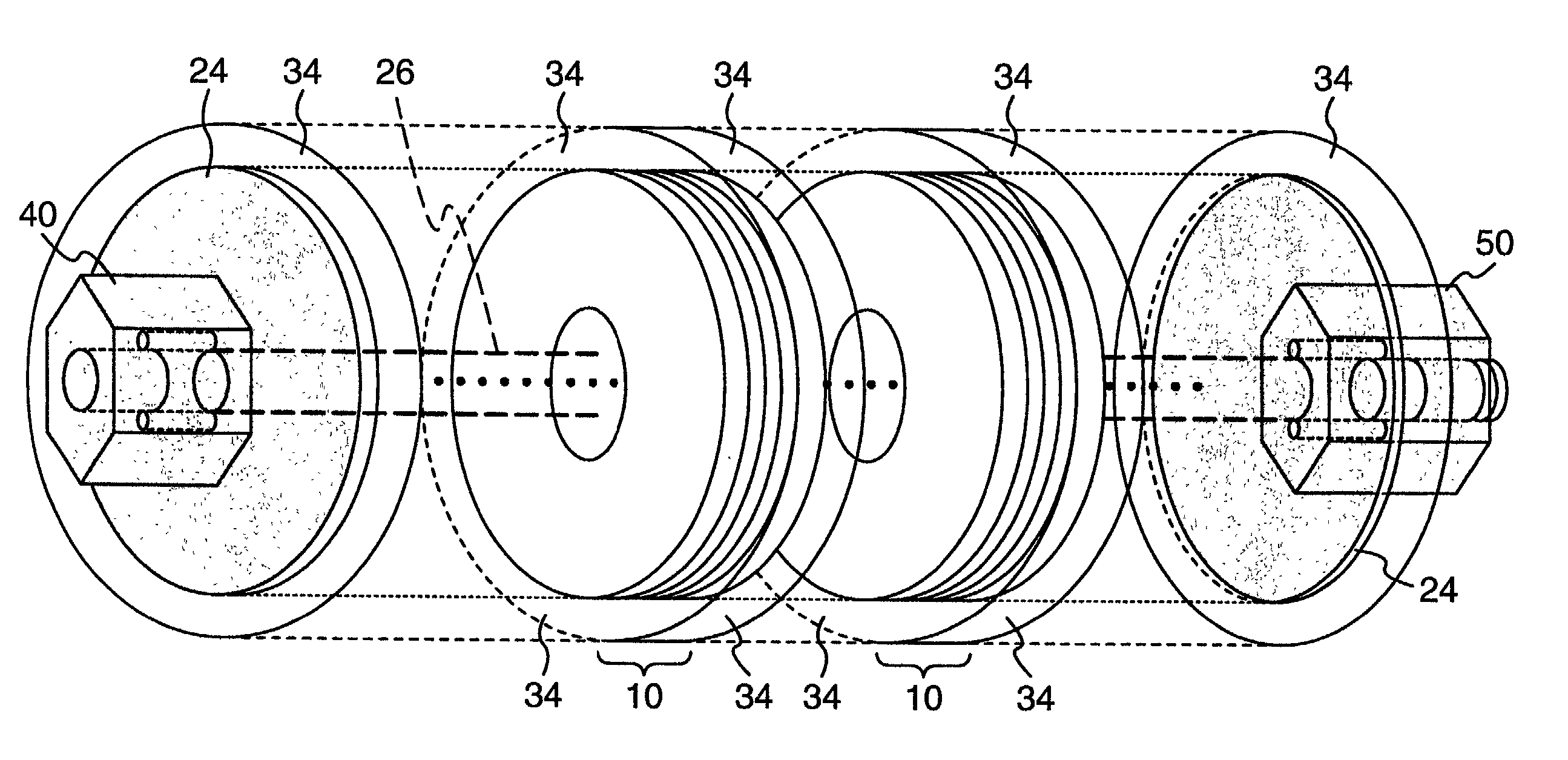
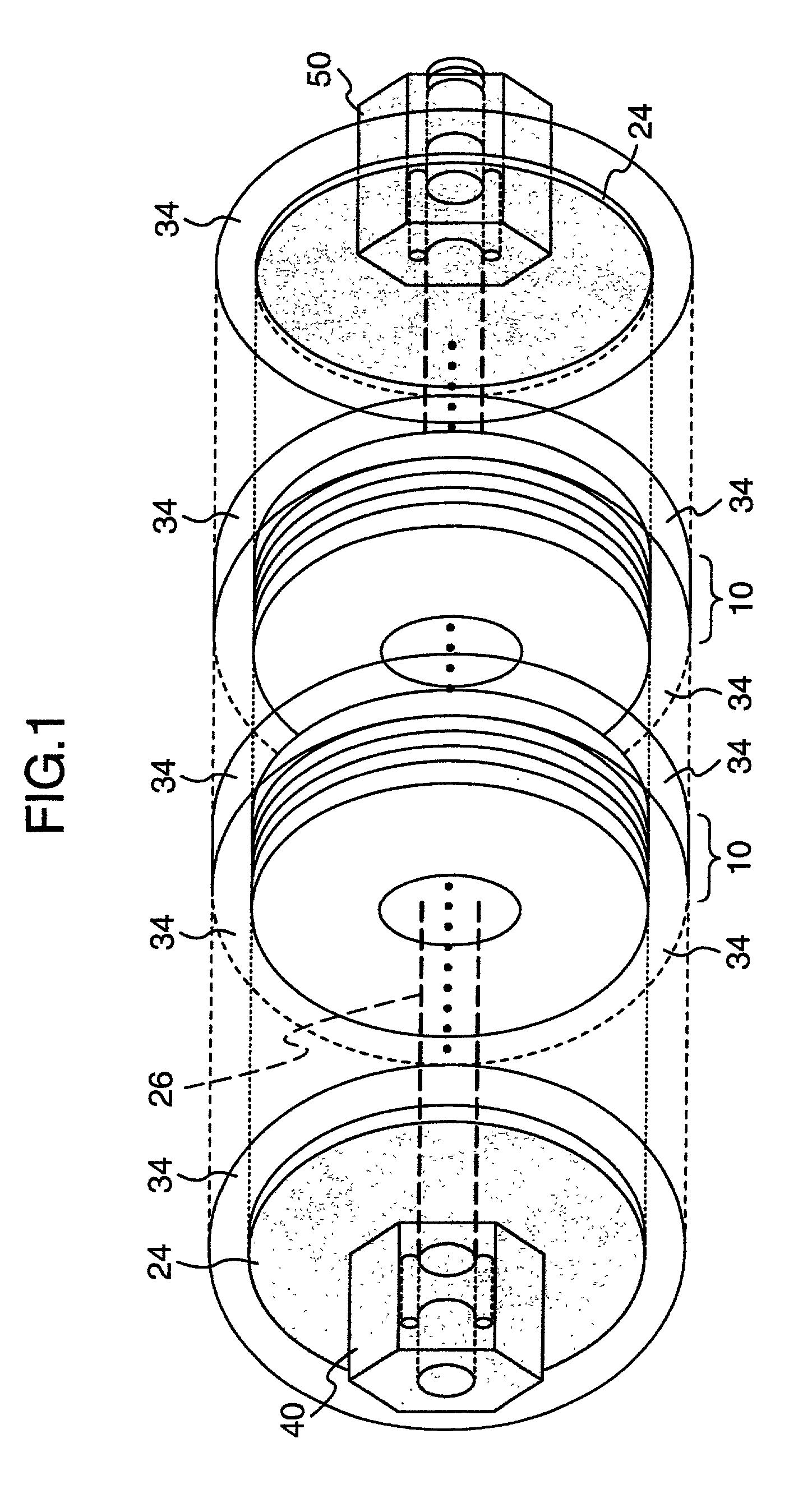
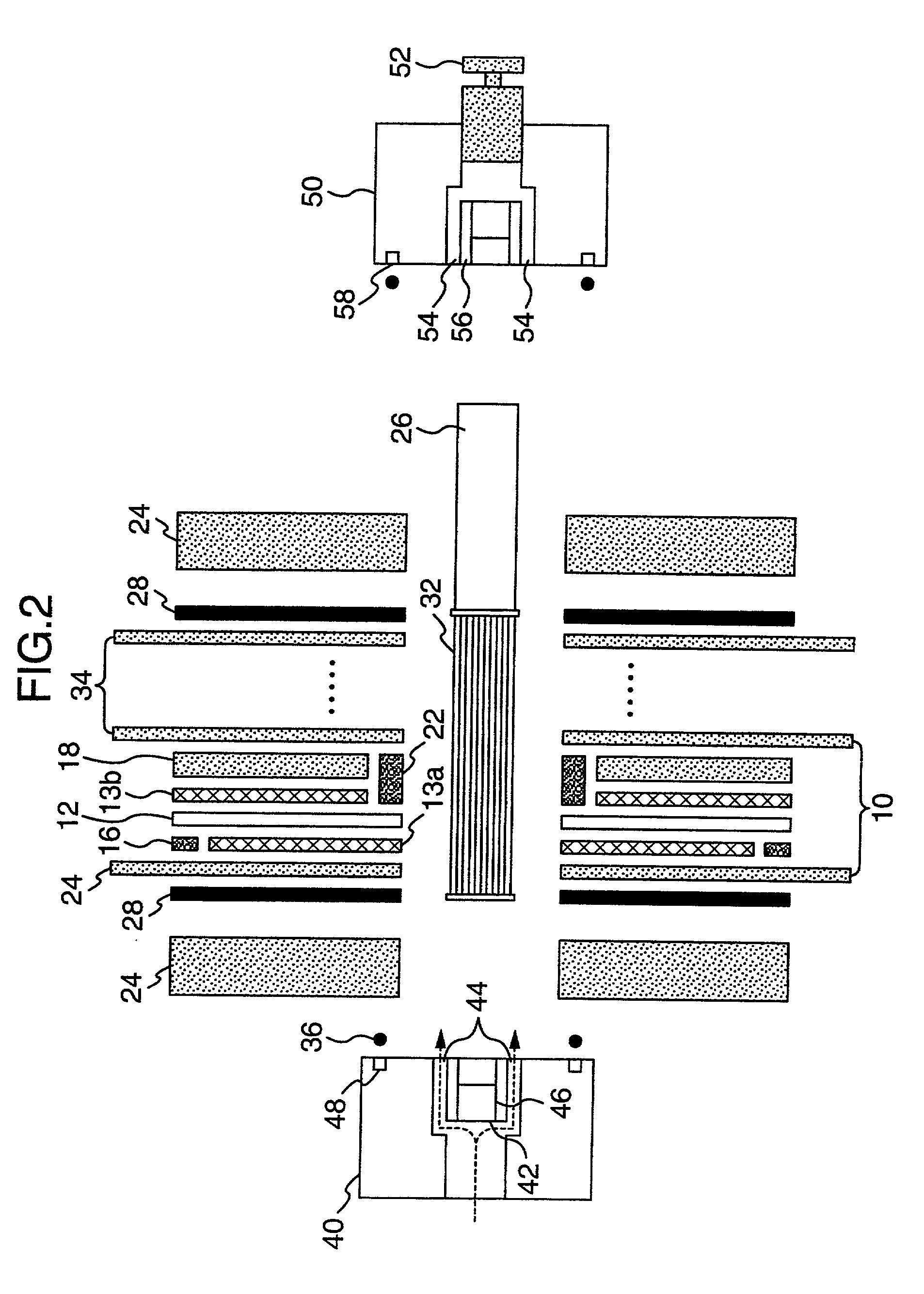
[0028] FIG. 1 is a perspective view of the assembled condition of a portable fuel cell stack according to one embodiment of the invention and FIG. 2 is an exploded sectional view of this portable fuel cell stack. This portable fuel cell stack is called a solid polymer electrolyte fuel cell stack in which a fuel of hydrogen, etc. is used. This portable fuel cell stack includes a solid polymer electrolyte membrane 12, which is formed from a perfulorocarbon sulfonic acid polymer material of 0.05 mm thickness, between stainless steel separator plates 34 of 0.3 mm thick having a larger diameter than other members, a fuel electrode 13a having a size of 0.5 mm thickness, an inside diameter of 15 mm and an outside diameter of 45 mm and an oxygen electrode 13b having a size of 0.5 mm thickness, an inside diameter of 19 mm and an outside diameter of 55 mm, which are arranged on both s...


PUM


Abstract

A portable fuel cell stack is provided in which the number of components is reduced by reducing the number of flow field plates, cell performance is improved by reducing the number of contact portions to thereby lower internal resistance, and fuel is supplied from the center of an end plate directly to a fuel distribution manifold. The portable fuel cell stack includes two end plates, a plurality of unit cells positioned between the two end plates, a fuel distribution manifold positioned in the center of the unit cell for fuel supply thereto, a tie bolt passed through the centers of the fuel manifold and the unit cell for integration of these members, and fixing nuts threaded to both ends of the tie bolt for integrally clamping the plurality of unit cells together between the end plates via an O-ring, etc. The unit cell includes a polymer electrolyte membrane, an oxygen electrode and a fuel electrode installed on both sides of the polymer electrolyte membrane, a flow field plate adjacent to the oxygen electrode side, and a separator plate on the outside of the flow field plate adjacent in contact therewith and another separator plate on the outside of the fuel electrode side in contact therewith. One of the fixing nuts has a fuel supply port connecting to the fuel distribution manifold.

Description

BACKGROUND OF THE INVENTION[0001] The present invention relates to a portable fuel cell stack which can be used in various applications, such as a power source for outdoor activities and picnics and a household generator, and which uses light, silent and pollution-free solid polymer cells.[0002] Fuel cell stacks generally use hydrogen as a main fuel and take out the energy generated during the chemical reaction of this hydrogen with oxygen. There are several types of fuel cell stack and one type is a solid polymer electrolyte fuel cell stack. This solid polymer electrolyte fuel cell stack has features such as low operating temperature and high output density.[0003] An example of fuel cell stack in which such conventional solid polymer electrolyte fuel cell stack is disclosed in U.S. Pat. No. 5,595,834. As shown in FIG. 5, a unit cell 10 comprises a solid polymer electrolyte membrane 12, an anode (fuel electrode) 13a and a cathode (oxygen electrode) 13b, which are provided on both si...

Claims


Application Information

Patent Timeline
IPC IPC(8): H01M8/10H01M8/02H01M8/24
CPCH01M8/241H01M8/248H01M8/2485H01M8/04225Y02B90/18H01M8/0271H01M8/2484H01M2250/30Y02B90/10Y02E60/50H01M8/04
Inventor KITAGAWA, KOJIKATO, EIJINARUSE, YUKIOINABA, TAKASHIIDO, YASUO
Owner DAIDO METAL CO LTD
Learn More