Radio frequency (RF) detector with a light emitting diode (LED) indicator

a technology of light-emitting diodes and radio frequency detectors, applied in the direction of indicating the presence of current/voltage, transmission monitoring, wireless communication, etc., can solve the problems of no reception, no reception, and many efforts to determine whether the subscriber is receiving adequate rf signals

Inactive Publication Date: 2002-09-12
CISCO TECH INC
View PDF6 Cites 17 Cited by
  • Summary
  • Abstract
  • Description
  • Claims
  • Application Information

AI Technical Summary

Problems solved by technology

The absence or insufficiency of the RF signal may be caused by cable that is cut in the field or within a home, or may be due to inherent cable losses, the transmitted RF signal be...

Method used


Image

  • Radio frequency (RF) detector with a light emitting diode (LED) indicator
  • Radio frequency (RF) detector with a light emitting diode (LED) indicator
  • Radio frequency (RF) detector with a light emitting diode (LED) indicator

Examples


Embodiment Construction

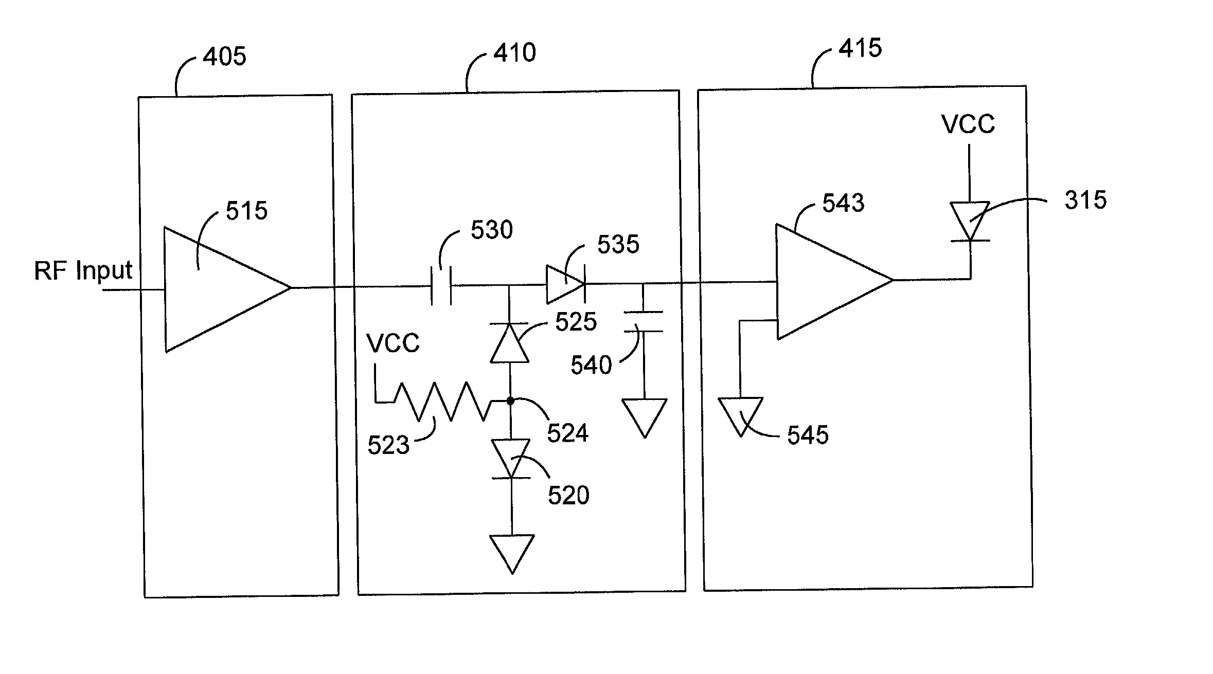
[0011] In accordance with the present invention, FIG. 3 illustrates a drop amplifier that includes an RF detector for providing a visual indication that RF signals are present within the drop amplifier 300, which supplies an amplified RF signal to the subscriber. U.S. Pat. No. 6,161,011 to Loveless, the teachings of which are incorporated herein by reference, shows a hybrid fiber coax communications system in which one could implement the drop amplifier 300 and RF detector of the present invention.

[0012] The drop amplifier 300 is generally installed on the outside of a subscriber's home, or alternatively, placed within the home. An input port 305 receives the RF signals from a distribution tap installed within the broadband communications system. Amplification circuitry 308 then boosts the RF signals sufficiently enough for the requirements of the subscriber. Typically, the drop amplifier 300 will amplify the RF signals by seven to fifteen decibels (dBs). The amplification within th...


PUM


Abstract

A broadband communications system for providing radio frequency (RF) signals to subscriber equipment that includes an amplifier for amplifying the RF signals and for providing an indication of the presence of the RF signals. The amplifier includes an input for receiving the RF signals, a first gain circuit for amplifying the RF signals and providing amplified RF signals, and an output for providing the amplified RF signals to the subscriber equipment. An RF detector included within the amplifier where there is a tap circuit for diverting a portion of the amplified RF signals, the tap circuit connected between the first gain circuit and the output, a gain circuit for amplifying the diverted RF signals, a rectification circuit for converting the amplified diverted RF signal to a DC voltage, a comparator for comparing the DC voltage to a reference voltage, and an indicator connected to the comparator for indicating when the DC voltage exceeds the reference voltage, whereby the DC voltage exceeding the reference voltage indicates the presence of an RF signal.

Description

FIELD OF THE INVENTION[0001] This invention relates generally to broadband communications systems, such as cable television systems, and the electronic devices used in such systems, and more specifically, to drop amplifiers with RF signal detection devices.BACKGROUND OF THE INVENTION[0002] A communication system 100, such as a two-way cable television system, is depicted in FIG. 1. The communication system 100 includes headend equipment 105 for generating forward signals that are transmitted in the forward, or downstream, direction along a communication medium, such as a fiber optic cable 110, to an optical node 115 that converts optical signals to radio frequency (RF) signals. The RF signals are further transmitted along another communication medium, such as coaxial cable 120, and are amplified, as necessary, by one or more distribution amplifiers 125 positioned along the communication medium. Taps 130 included in the cable television system 100 split off portions of the forward si...

Claims


Application Information

Patent Timeline
IPC IPC(8): G01R19/145H04B1/38
CPCG01R19/145H04B1/3833
Inventor MARTINE, JOSEPH W.WALLIS, DAVID W.
Owner CISCO TECH INC
Why Eureka
Try Eureka