Method for radius limit adjustment on radius conveyor belts

a technology of radius limit and conveyor belt, which is applied in the field of plastic modular conveyor belts, can solve the problems of limited collapse degree, and achieve the effect of preventing or minimizing the chatter or stick and slip action

Inactive Publication Date: 2002-09-19
KVP PLASTIC BELTING +2
View PDF0 Cites 15 Cited by
  • Summary
  • Abstract
  • Description
  • Claims
  • Application Information

AI Technical Summary

Benefits of technology

[0008] Modification of the radius can be accomplished in several different ways. One method is to place at the inner side of the basic radius conveyor belt modules that are restricted to a more limited degree of collapse than the other modules, due to having shorter slotted apertures than the other modules, or other structural limitations to collapsing together. This can be done in every row, alternate rows, or every third row, etc., in regular fashion so as to restrict the ability of the belt to collapse together at the inner side in a way such as to limit the overall minimum radius of curvature of the belt, so that the row ends are substantially fully collapsed and bearing against one another at the inside of the curve, preventing chatter and vibration.
[0009] Another method for restricting curvature is to use a uniform array of modules, but to add restricting devices to modules at the inner side of the belt relative to curves. These restricting devices can be shims or stops placed in some of the slotted apertures or in other areas of the belt, such as against a center bar of the belt between adjacent projecting link ends, so as to prevent full collapsing together of the belt modules.
[0013] It is thus among the objects of the invention to substantially match the minimum radius of curvature of a plastic modular conveyor belt to the actual curves of an installation for which the belt is designated, the method comprising modifying a basic set of modules (whether the basic conveyor belt is actually assembled with such modules or not) to restrict the minimum possible radius of the basic belt and thus to modify the belt to fit a particular curvature, and thereby to prevent or minimize chatter or "stick and slip" action at the inner edge of belt curves. These and other objects, advantages and features of the invention will be apparent from the following description of a preferred embodiment, considered along with the accompanying drawings.

Problems solved by technology

One method is to place at the inner side of the basic radius conveyor belt modules that are restricted to a more limited degree of collapse than the other modules, due to having shorter slotted apertures than the other modules, or other structural limitations to collapsing together.

Method used


Image

  • Method for radius limit adjustment on radius conveyor belts
  • Method for radius limit adjustment on radius conveyor belts
  • Method for radius limit adjustment on radius conveyor belts

Examples


Embodiment Construction

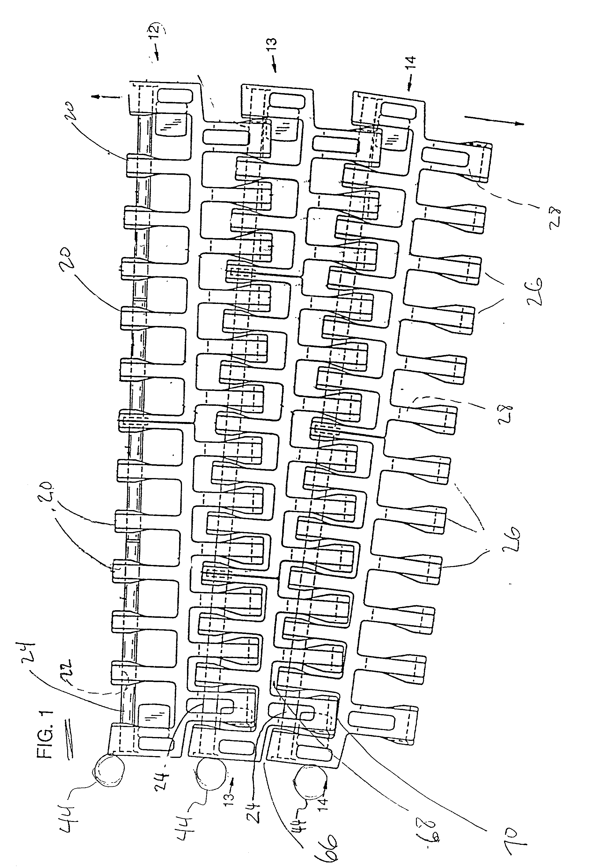
[0019] In the drawings, FIG. 1 shows a portion of a plastic modular belt 10 capable of travel around curves, and this belt can be considered a basic radius modular conveyor for purposes of the invention. This belt is essentially as described in U.S. Pat. Nos. 5,181,601 or 4,901,844. As is well-known, the belt has rows of modules 12, 13, 14, etc., each of which has at least one module and usually more than one module side by side to make up the row. Facing in one direction from each module are a plurality of first projections or projecting link ends 20 which have apertures 22 to receive a connecting rod 24. The other set of link ends, which can be called a second set of projecting link ends 26, have slotted apertures 28 so that the inner edge of the assembled conveyor belt can collapse the modules together as the belt travels around the curve, the collapsed edge being the inside edge.

[0020] As explained above, these belts are often guided around the inside of the curve in the conveyo...


PUM

PropertyMeasurementUnit
radius of curvatureaaaaaaaaaa
lengthaaaaaaaaaa
widthaaaaaaaaaa

Abstract

Plastic conveyor belts made up of modules interconnected by transverse rods and capable of straight or radius travel are adjusted as to minimum radius the belt can traverse by restricting collapsibility at the inner edge of the belt. This can be accomplished using shims in the slotted apertures of link ends, preventing full rod travel in those apertures, at each row or at alternating or selected rows of the belt; or shims otherwise placed in the belt to prevent full collapse; or by using different modules in certain rows, with less collapsibility; or by substituting different edge modules in belts of multiple modules per row. In this way, a basic radius conveyor belt can be defined, with a relatively tight minimum radius, and then can be modified so as to be custom-fitted to spiral conveyor or other belt systems having specific curve radii which are larger than the radius of the basic belt. By substantially matching the conveyor belt's minimum achievable radius to the actual radius in service on the conveyor belt system, better driving performance is achieved, eliminating belt edge chatter and vibration.

Description

BACKGROUND OF THE INVENTION[0001] This invention concerns plastic modular conveyor belts, and is particularly concerned with such conveyor belts of the radius type, that travel around curves as well as straight paths, and with fitting a belt of a certain minimum radius to a particular radius of curvature in a spiral conveyor system or in other radius conveyor travel.[0002] Radius conveyor belts of the type with which this invention is concerned are shown in U.S. Pat. Nos. 4,742,907, 4,901,844, 5,181,601 and 5,573,105. So called spiral conveyor belts, which travel in a helical path as driven by a driving cage or tower, are shown or described in U.S. Pat. Nos. 4,901,844 and 5,069,330.[0003] Spiral conveyors are often fitted with modular plastic radius-type conveyor belts which have a certain minimum radius of curvature. These belts are used to fit a variety of different radii of driving tower on the spiral systems, and thus are often not matched even approximately to the actual radius...

Claims


Application Information

Patent Timeline
Patent Type & Authority Applications(United States)
IPC IPC(8): B65G17/08B65G17/38B65G21/18
CPCB65G17/086B65G17/385B65G21/18B65G2201/02B65G2207/24Y10T29/49716
Inventor PALMAER, ERIC K.KUCHARSKI, JOHNBICKEL, JR, WILLIAM J
Owner KVP PLASTIC BELTING
Why Eureka
Try Eureka