Combination pressure sensor with capactive and thermal elements

a technology of capactive and thermal elements, applied in the direction of fluid pressure measurement using capacitance variation, instruments, measurement devices, etc., can solve the problems of inability to operate in higher pressure ranges, inability to reliably measure higher pressures above a few 10 mbar, inaccurate, etc., to achieve economic production form, high accuracy, and convenient handling

Inactive Publication Date: 2002-09-19
UNAXIS BALZERS AG
View PDF0 Cites 9 Cited by
  • Summary
  • Abstract
  • Description
  • Claims
  • Application Information

AI Technical Summary

Benefits of technology

[0009] It is the object of the invention to provide a pressure sensor which covers a large measuring range--preferably from about 10.sup.-6 mbar to a few bar--and at the same time has a simple design and is compact and economical and insensitive to contamination. This object is achieved by the features in the claims.
[0010] It is also intended to provide a pressure measuring apparatus which is distinguished by the same characteristics as the pressure sensor according to the invention and which can be mounted easily, in any position and quickly, and furthermore a pressure measuring apparatus which combines these advantages with a very large measuring range with high accuracy and stability.
[0011] Finally, it is intended to provide a method for monitoring the pressure in a chamber, which is sufficiently accurate and stable in the long term over a large measuring range.
[0012] The pressure sensor according to the invention combines a capacitive measuring element with a thermal conductivity measuring element in compact, easily handled and economically producible form. The upper pressure range above about 0.1 mbar is covered by the capacitive measuring element independent of the type of gas, and the lower pressure range from about 10.sup.-6 mbar to about 10 mbar by the thermal conductivity measuring element, for example averaging being performed in the overlap region. Consequently, pressures between about 1 mbar and a few bar can be measured independently of the type of gas and with high accuracy (in general about 1%), while at the same time the measuring range extends down to about 10.sup.-6 mbar with generally sufficient accuracy of measurement.
[0014] The pressure measuring apparatuses according to the invention have the advantages of the pressure sensor according to the invention and are convenient and easy to mount. When supplemented by suitable further measuring elements, they have a compact design and can measure the pressure in a wide measuring range with high accuracy.
[0015] The method according to the invention makes it possible to monitor the pressure in a chamber in a stable manner over a long time, in spite of the offset problems of capacitive measuring cells. These advantageous characteristics are displayed in particular in the monitoring of the pressure in locks since, owing to the cyclic pressure changes, the offset can be regularly compensated here.

Problems solved by technology

Furthermore, such pressure sensors always have an offset problem which can cause considerable inaccuracies, particularly in the longer term.
10.sup.-6 mbar, but in this case higher pressures above a few 10 mbar can no longer be reliably measured.
They are not capable of functioning in higher pressure ranges and are inaccurate from about 10.sup.-2 mbar.
These and similar solutions are, however, expensive owing to the associated technical complexity.
The distance between the measuring elements can lead to uncertainty in the measured result.
Moreover, the offset problem persists even when a plurality of such measuring elements are used.
Although the apparatus is compact and can measure the total above-mentioned measuring range, it is very inaccurate in the upper part.
Here, the corresponding pressure measuring apparatus is relatively inconvenient.
Moreover, the spatial separation of the measuring elements may give rise to uncertainties in the measured result.

Method used


Image

  • Combination pressure sensor with capactive and thermal elements
  • Combination pressure sensor with capactive and thermal elements
  • Combination pressure sensor with capactive and thermal elements

Examples


Embodiment Construction

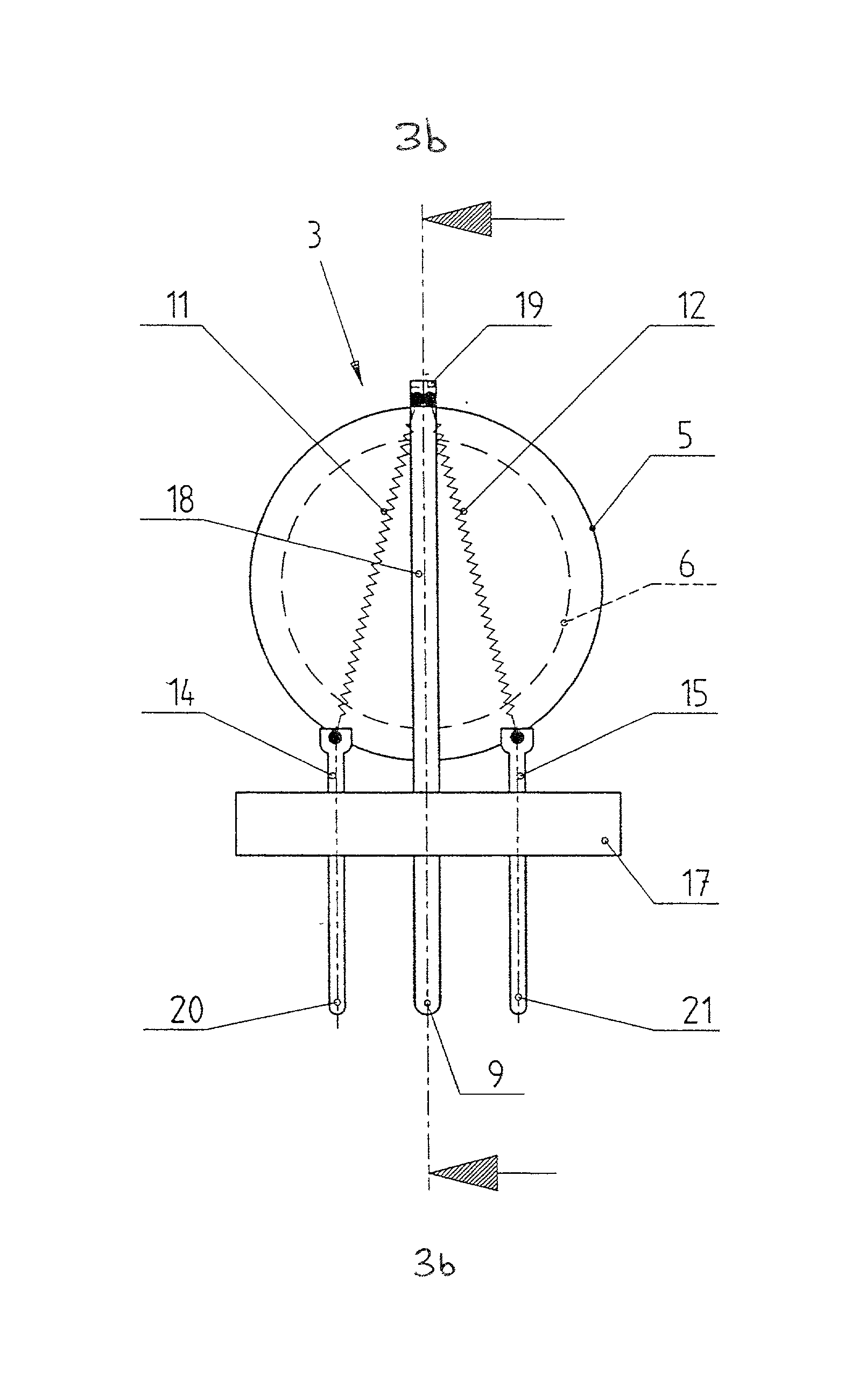
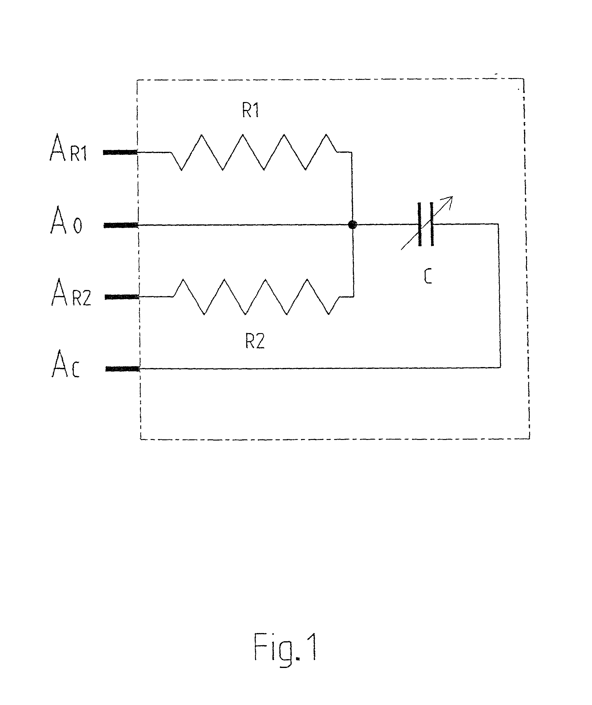
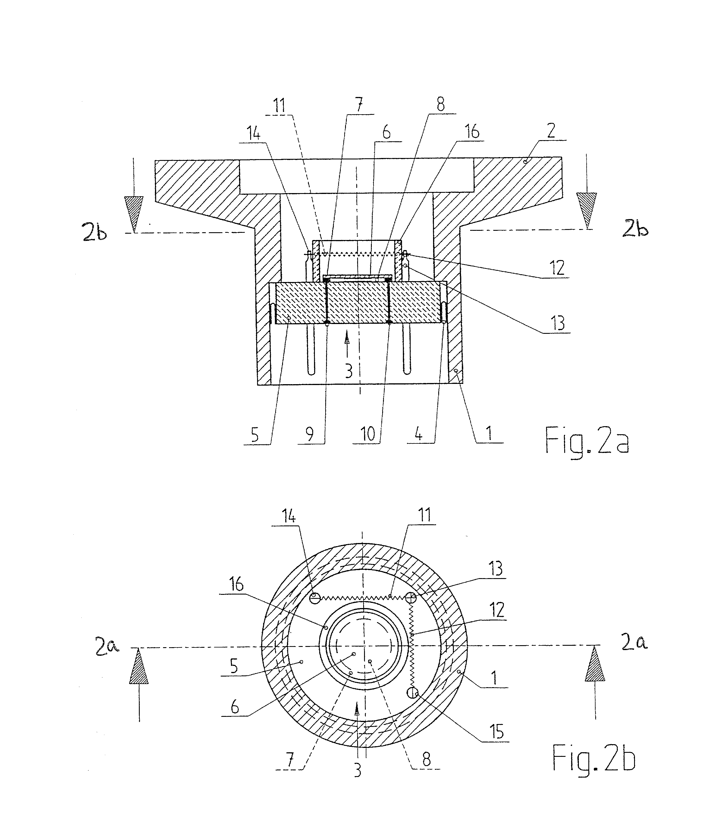
[0029] The pressure sensor according to the invention is arranged in a vessel or a chamber and (FIG. 1) is designed in principle so that a capacitive measuring element having a capacitance C whose value is dependent on the gas pressure is arranged between the earth connection A.sub.0 and a capacitor connection A.sub.c. Its value is monitored in a known manner by means of a suitable evaluation circuit, which derives a first pressure signal from it. The first pressure signal is derived by means of an essentially linear characteristic from the original value reproducing the value of the capacitance C. The offset which usually occurs in the case of capacitive measuring elements and impairs the long-term stability can be compensated by a method described further below.

[0030] A first resistor R.sub.1 and a second resistor R.sub.2, which represent heating elements of a thermal conductivity measuring element, are arranged between the earth connection A.sub.0 and a first resistor connection ...


PUM

PropertyMeasurementUnit
distanceaaaaaaaaaa
thicknessaaaaaaaaaa
thicknessaaaaaaaaaa

Abstract

A pressure sensor has a baseplate and a support plate with a membrane. Layers on the membrane and the support plate are connected to a circuit for capacitively measuring pressure to generate a first pressure signal. A thermal conductivity measuring element that generates a second pressure signal has a heating element connected to the baseplate adjacent the support plate at a location opposite from the membrane for protecting the membrane from thermal effects. The method uses the sensor apparatus to generate an output signal representing a measured result when the measured result is above a transition value, on the basis of the first pressure signal and, when the pressure falls below a threshold value, any offset of the first pressure signal is compensated in such a way that determination of the output signal on the basis of the first pressure signal leads to the same result as determination of the output signal on the basis of the second pressure signal.

Description

CROSS REFERENCE TO RELATED APPLICATIONS[0001] This is a continuation of application No. 09 / 720,889 filed Mar. 2, 2001, now abandoned, which was a Rule 371 continuation of International Application PCT / CH99 / 00325, filed Jul. 16, 1999, and is a continuation-in-part of application No. 09 / 116,666, filed Jul. 16, 1998, which is now U.S. Pat. No. 5,962,791.FIELD AND BACKGROUND OF THE INVENTION[0002] The invention relates to a pressure sensor, a pressure measuring apparatus which comprises such a pressure sensor, and a method for monitoring the pressure in a chamber by means of such a pressure sensor or pressure measuring apparatus.PRIOR ART[0003] Known pressure sensors of the generic type (cf. for example EP-A-0 351 701) contain only a capacitive measuring element consisting of a support plate and a membrane, which carry electrically conductive layers. Although measurement can be carried out independently of the type of gas and with high accuracy between about 10.sup.-6 mbar and 10 bar by...

Claims


Application Information

Patent Timeline
Patent Type & Authority Applications(United States)
IPC IPC(8): G01L9/00G01L21/12
CPCG01L9/0075G01L21/12
Inventor WALCHLI, URSBJORKMAN, PERSTOCKER, RUDOLFGANTNER, MARCEL
Owner UNAXIS BALZERS AG
Why Eureka
Try Eureka