Permanent magnet type three-phase AC rotary electric machine

Inactive Publication Date: 2002-09-19
YAMAHA MOTOR ELECTRONICS CO LTD
View PDF4 Cites 35 Cited by
  • Summary
  • Abstract
  • Description
  • Claims
  • Application Information

AI Technical Summary

Benefits of technology

0010] This invention is adapted to be embodied in a permanent magnet type three-phase AC rotary electric machine including a permanent magnet element and a coil winding element. These elements are relatively rotatable. The coil winding element is wired in three phases connected to a line current circuit. Each phase is comprised of a parallel circuit formed by connecting a plurality of series circu

Problems solved by technology

However, when a coil wire having a large diameter is used, the efficiency of winding the coil wire on magnetic pole teeth is significantly lowered.
The resulting processing is slow and difficult resulting in reduced production capacity and high cost.
Additionally, the connections at coil terminals are unavoidably large, resulting in a large-size winding assembly and co

Method used


Image

  • Permanent magnet type three-phase AC rotary electric machine
  • Permanent magnet type three-phase AC rotary electric machine
  • Permanent magnet type three-phase AC rotary electric machine

Examples


Embodiment Construction

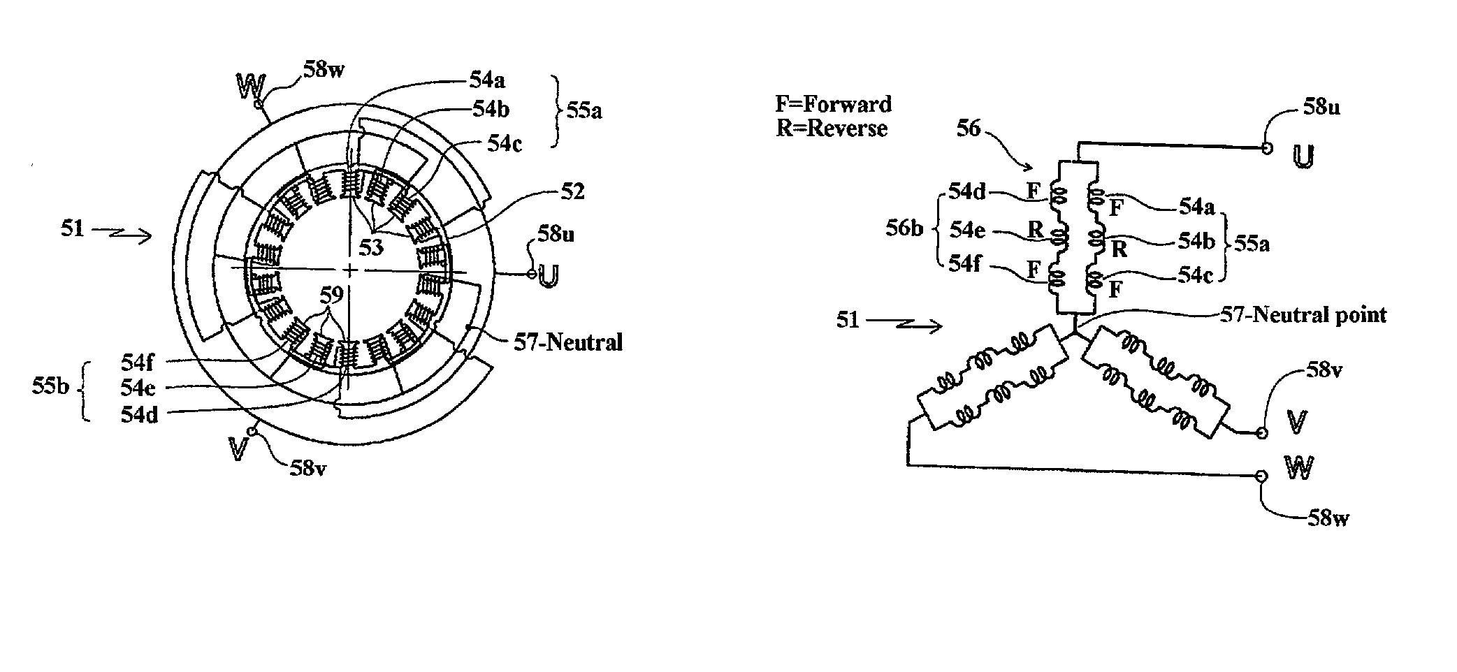
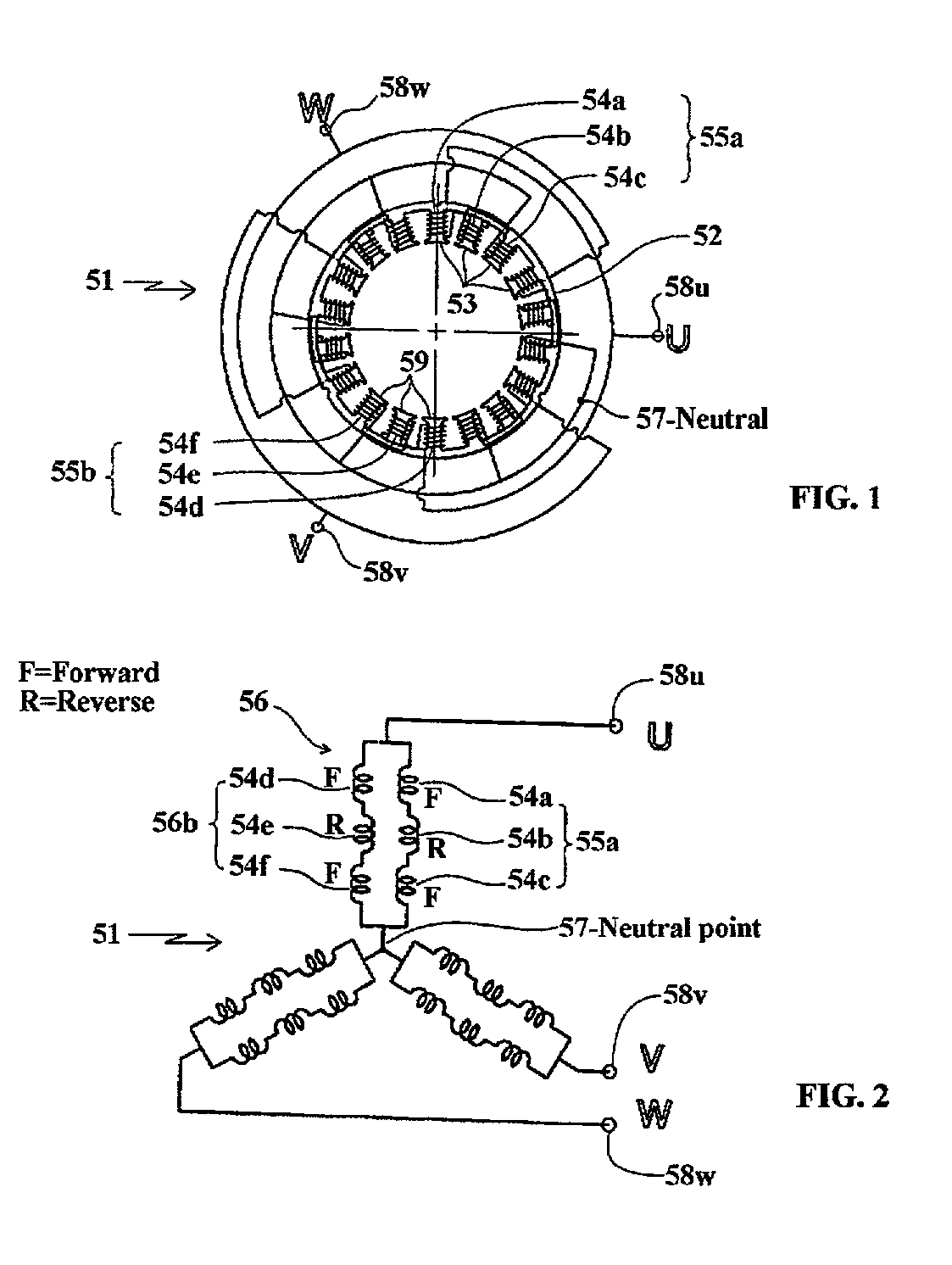
[0032] Referring first to FIGS. 1 and 2, these figures show the construction of a first embodiment of the invention comprised of a 18-slot, 16-pole generator or motor, identified generally by the reference numeral 51. In the illustrated embodiments the coil winding element, indicated generally by the reference numeral 52, forms the stator and is wired in a Y arrangement. As will be apparent the coil winding element 51 may also comprise the rotor.

[0033] In FIG. 1, designated as 52 is an annular stator coil winding element having 18 magnetic pole teeth 53 extending radially inward. On each of the magnetic pole teeth 53 is wound a stator coil 54. A rotor or permanent magnet element (not shown) to which 16 permanent magnets are circumferentially fixed in an alternate fashion is rotatably held inside the stator 52. Namely, a permanent magnet type rotor having 16 poles rotates in the stator 52 having 18 slots (ditches). As noted above, the stationary and rotating elements may be reversed....


PUM


Abstract

Several embodiments of permanent magnet type three-phase AC rotary electric machines wherein the phase current flow is formed by parallel circuits formed by a plurality of serial circuits each comprising one or a plurality of stator coils so that electromagnetic voltage or counter electromagnetic voltage generated across opposite ends of the plural serial circuits may be always almost the same. Thus, a circulating current does not flow in the parallel circuits, whereby the efficiency of the rotary electric machine can be improved. Also, since the line current circuit of each of the phases is constituted of a parallel circuit, the current flowing in each of the stator coils is small so that the diameter of the stator coil wire can be small. Thus, the winding of the coils can be improved. Also, the processing of the coil terminals is facilitated and the processed portions of the terminals can be made small, resulting in a compact rotary electric machine.

Description

BACKGROUND OF INVENTION[0001] This invention relates to a rotary multi-phase electrical machine, such as a three-phase AC generator and a three-phase AC motor and more particularly to an improved coil winding arrangement therefore.[0002] Three-phase AC generators or motors are well known for many applications. Brushless electric motors are examples of machines of this type. In the conventional rotary electric machine, connected coil winding coils formed on magnetic pole teeth cooperate with permanent magnets. Upon relative rotation of the coil windings and permanent magnets, an electromotive force is induced in each coil (in the case of a generator) or a torque is generated in the rotor (in the case of a motor). The electromotive force or a counter electromotive force generated in each phase or line is the vector sum of effects of the coils in each phase or line.[0003] In rotary electric machines widely used in home appliances or for industrial applications, the supply or output vol...

Claims


Application Information

Patent Timeline
IPC IPC(8): H02K3/28H02K3/18H02K21/14H02K21/16
CPCH02K3/28H02K21/16
Inventor ANMA, TATSUYATAKANO, TADASHI
Owner YAMAHA MOTOR ELECTRONICS CO LTD
Why Eureka
Try Eureka