Disk cartridge

a technology of disks and cartridges, applied in the direction of casings/cabinets/drawers, instruments, casings/cabinets/drawers, etc., can solve the problems of dust or the like adhesion to the the surface of the cover layer is not easy to be disregarded, and the effect of dust or the like on the adhesion to the surface cannot be ignored

Inactive Publication Date: 2002-09-19
FUJIFILM HLDG CORP +1
View PDF13 Cites 14 Cited by
  • Summary
  • Abstract
  • Description
  • Claims
  • Application Information

AI Technical Summary

Problems solved by technology

However, if the thickness of the cover layer is reduced, the surface of the cover layer, i.e., an aperture of the laser beam at a surface exposed to the outside becomes smaller, and an influence of dust or the like adhering to the surface of the cover surface cannot be disregarded.
However, when the front side wall of the disk cartridge is formed into an arcuate shape, a deficiency such as inaccurate contact with a sensor member 206 or 208 (in this case, a sensor member 206) in the drive device when the disk cartridge is inserted into the drive device may easily occur.
Therefore, the drive device and the disk cartridge may not be able to be uniquely positioned, thereby arising a problem that the center core cannot be accurately set with respect to the rotary spindle.
Consequently, the positional accuracy of the disk cartridge with respect to the drive device is liable to become unsta...

Method used


Image

  • Disk cartridge
  • Disk cartridge
  • Disk cartridge

Examples


first embodiment

[0165] In this manner, the disk cartridge 10 can be positioned with high accuracy via the projections 204, and further, the disk cartridge 10 can be prevented from being inserted farther. Moreover, it is possible to inhibit the opening 14 from being shut by the urging force of a torsion spring 124 or the disk cartridge 10 from being moved in a discharging direction. Thereafter, information is recorded on the recording side of the disk medium 20 or the information recorded on the recording side is reproduced by a rotary spindle and the recording / reproducing head. When the disk cartridge 10 is discharged from the drive device, the projections 204 are withdrawn from the reference holes 150 and 152, respectively, and thus, the disk cartridge 10 can be discharged in the same manner as in the

[0166] The guide grooves 146 and 148 are formed by cutting away the bottom plate 36 with high moldability. The formation of the guide grooves 146 and 148 enables the projecting height of the positioni...

third embodiment

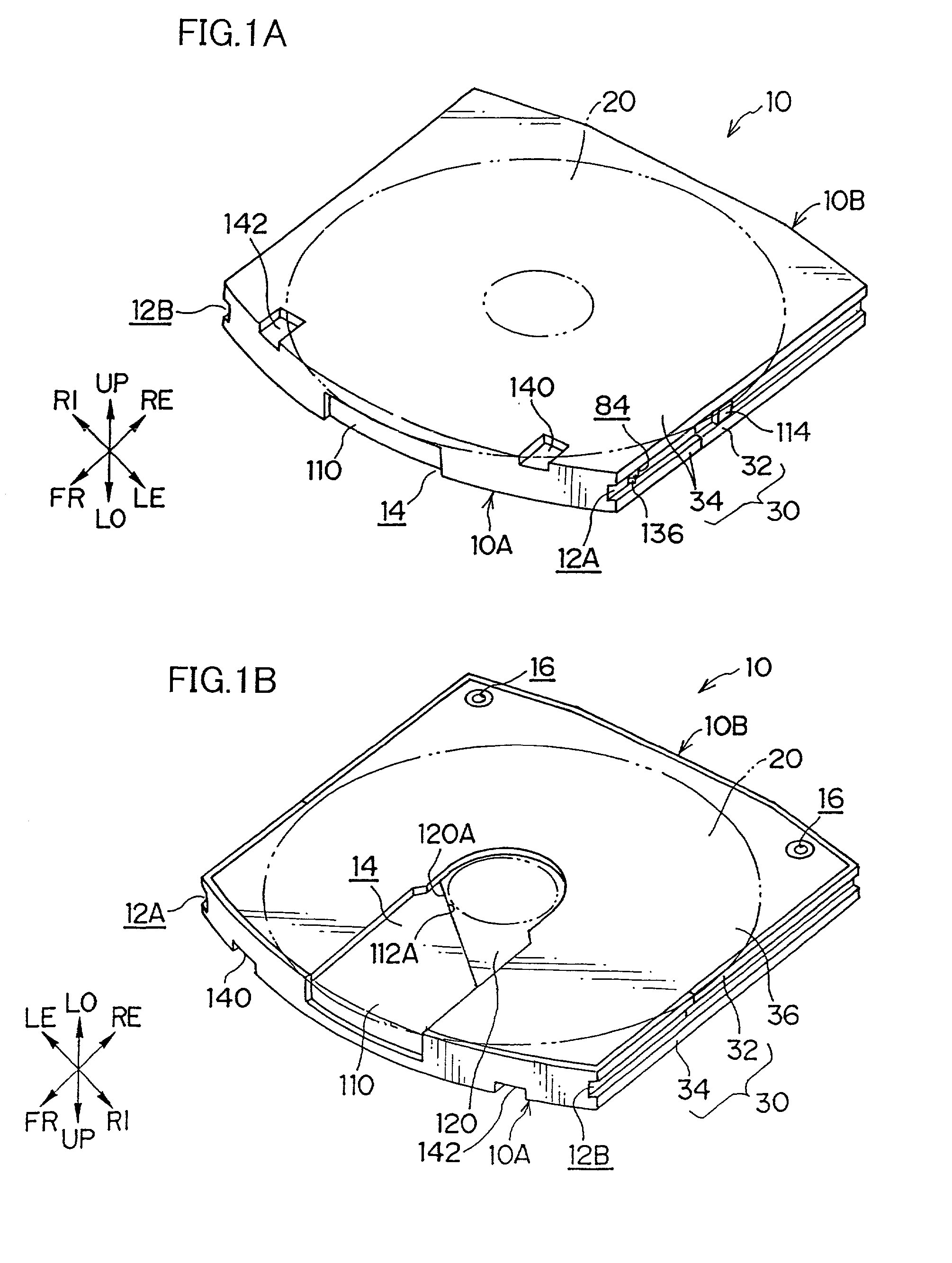
[0169] Next, a third embodiment according to the present invention will be described in reference to FIGS. 14 to 17B. As shown in FIG. 14, two reference holes 160 for restricting (detecting) the position of a disk cartridge 10 in the drive device are formed symmetrically with each other in the vicinity of a rear end 10B at the lower surface of the disk cartridge 10. Furthermore, two reference surfaces 162 to be used as dimensional references in a height direction of the disk cartridge 10 are formed symmetrically with each other in the vicinity of a front end 10A.

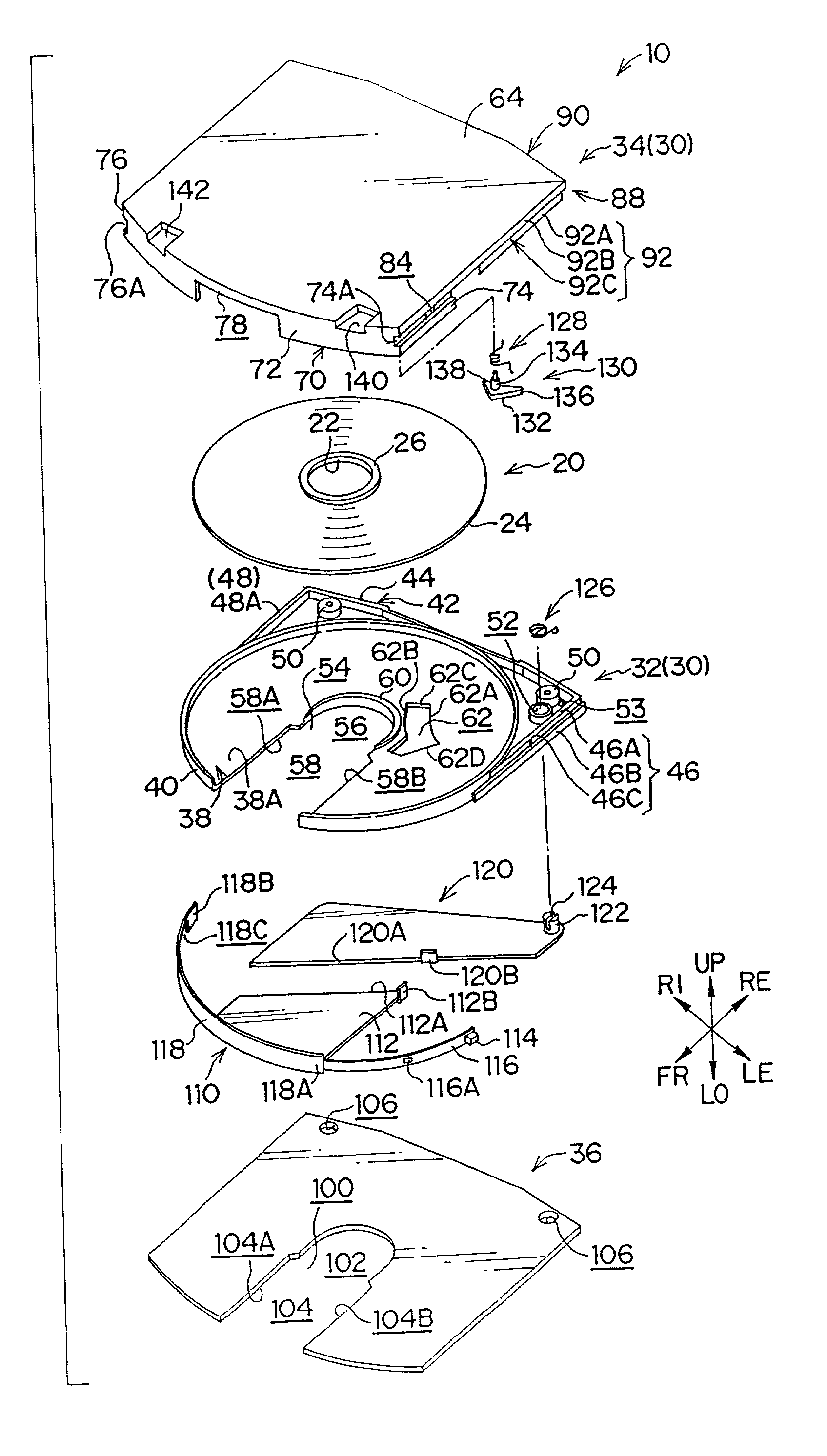
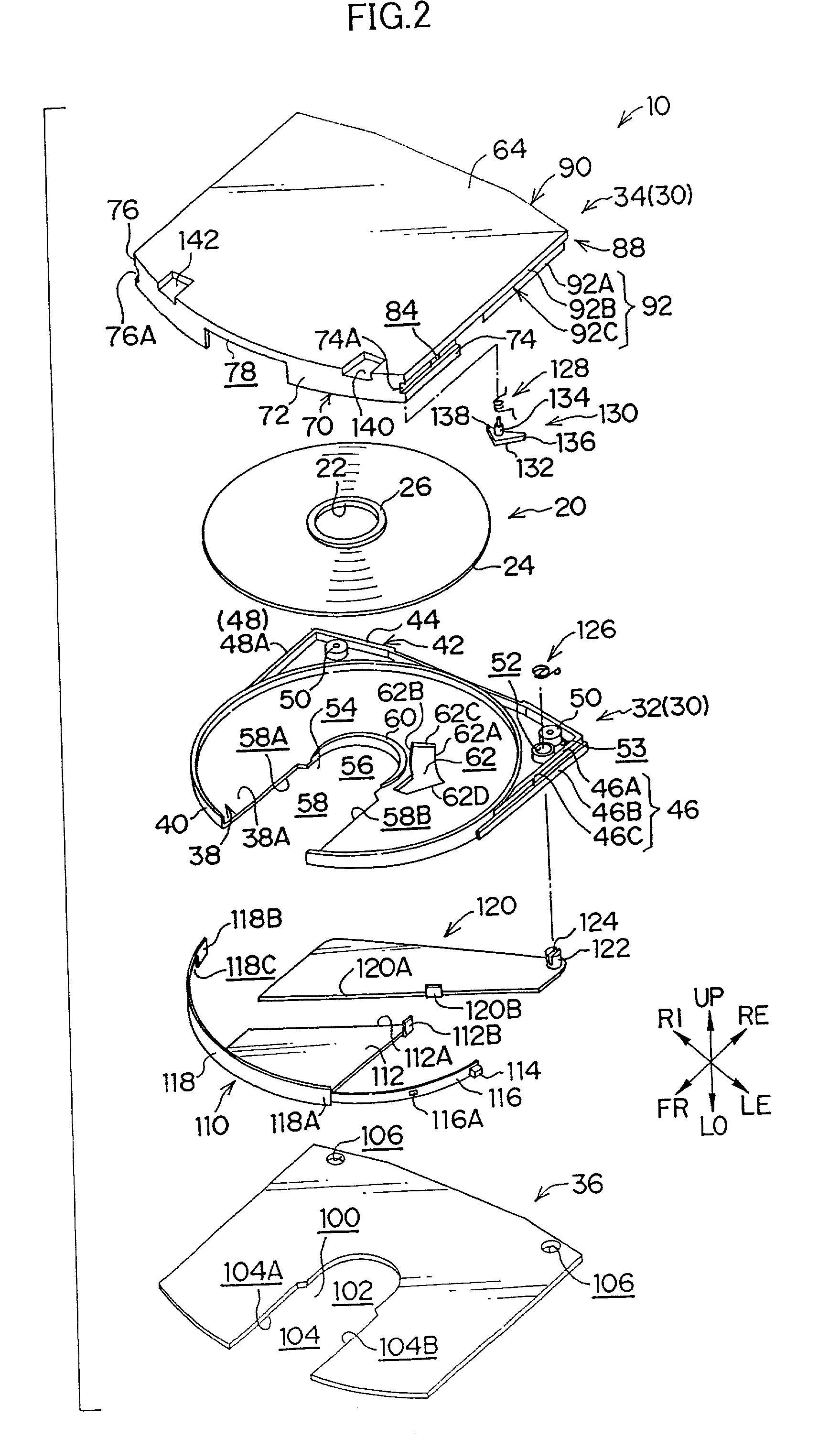
[0170] That is to say, as shown in FIGS. 15 and 16, through holes 144 are formed at both corners at a rear end of a base bottom 38 defined by a cylindrical wall 40 and a circumferential wall 42. Moreover, cylindrical bosses 164, each having a predetermined height, are formed at positions respectively corresponding to the through holes 144 between a circumferential wall 88 and an annular groove 68 at the lower surface 64A of ...

fourth embodiment

[0178] Next, a fourth embodiment according to the present invention will be described in reference to FIGS. 18 to 20. As shown in FIG. 18, reference holes 172 and 170 for positioning (i.e., detecting) a disk cartridge 10 in a drive device are provided near a front end 10A and a rear end 10B, respectively, and at the lower surface of the disk cartridge 10 in the vicinity of a first guide groove 12A at which an unlock lever 136 and a shutter engaging portion 114 are disposed. The reference hole 172 provided near the front end 10A is formed into a circular shape, and the reference hole 170 provided near the rear end 10B is formed into substantially a slot-like shape which has a major axis in a direction in which the disk cartridge 10 is loaded in the drive device.

[0179] That is to say, as shown in FIG. 19, a through hole 174 formed into substantially a slot-like shape which has a major axis in the direction in which the disk cartridge 10 is loaded in the drive device is provided at a r...


PUM


Abstract

The present invention relates to a disk cartridge, which can be accurately positioned with respect to a drive device for accessing a disk medium. The disk cartridge provided with a case rotatably accommodating a disk medium therein, an arcuate side wall which is directed forward when the case is loaded into the drive device, and a shutter member formed on at least one surface of the case, for opening or closing an opening for access to the disk medium. An engaging portion is provided at a side wall to engage with a sensor member disposed in the drive device for accessing the disk medium so as to record or reproduce information thereon.

Description

[0001] 1. Field of the Invention[0002] The present invention relates to a disk cartridge in which a disk medium to be used as a recording / reproducing medium for information processing or the like is rotatably accommodated while preventing any intrusion of dust or the like.[0003] 2. Description of the Related Art[0004] There has been conventionally used a disk medium such as an optical disk or a magneto-optical disk as a recording / reproducing medium for a portable computer. In such a disk medium, information is recorded by forming a pit, changing a phase or magnetizing, caused by decomposition of a pigment layer on a recording side by irradiating the recording side with a laser beam while the disk medium is rotated in the state in which it is loaded in a drive device. Moreover, such a disk medium is designed to reproduce the information recorded according to a reflectance ratio or a difference in polarizing angle of a laser beam.[0005] Furthermore, in such a disk medium, there has be...

Claims


Application Information

Patent Timeline
IPC IPC(8): G11B23/03
CPCG11B23/0308G11B23/0316
Inventor OISHI, KENGOHIRAGUCHI, KAZUO
Owner FUJIFILM HLDG CORP
Why Eureka
Try Eureka