Method for assembly level disk erase

a technology of assembly level and disk, applied in the field of improved, can solve the problems of high cost of prohibitively expensive to remove the disk and perform a disk level erase, and expensive hdd manufacturing assembly and/or test process, etc., to achieve improved hde level disk erase, improve the effect of hde level and low cost method

Inactive Publication Date: 2006-08-15
WESTERN DIGITAL TECH INC
View PDF7 Cites 11 Cited by
  • Summary
  • Abstract
  • Description
  • Claims
  • Application Information

AI Technical Summary

Benefits of technology

[0019]One embodiment of a method of the present invention comprises a fast, simple, low cost method of erasing one or more disk(s) (hereinafter, “disks”) of a disk drive while still at the HDE assembly level. The invention uses a specially shaped head / disk enclosure design along with a high strength magnetic field to erase the disks while the disks are in the HDE assembly. The invention allows an improved HDE level disk erase compared to more expensive or less efficient methods of disk erase. The invention also allows an improved HDE level disk erase compared to prior art by providing special HDE design features to enable a smaller magnetic gap.
[0020]The smaller magnetic gap of the disk erase apparatus enables a more efficiently produced magnetic flux density as well as increased magnetic flux density. The smaller magnetic gap also helps to provide a higher gradient of magnetic flux as a function of approach and insertion into the gap (stroke), thereby reducing exposure of magnetic damage of the motor rotor magnet. FIG. 5 shows a simplified HDD disk erase apparatus and its magnetic gap with thickness in direction Z and HDD insertion of stroke direction Y. A plot of the magnetic flux density (in direction X) as a function of gap and stroke is shown in FIG. 6.
[0021]The present invention comprises an HDD enclosure design that minimizes the thickness of the HDD in a localized region over the disk(s). This allows the source of the external magnetic field to be substantially closer to the disk recording media and a narrower working magnetic gap of the HDD level disk erase apparatus that provides two important benefits: (1) reduced stray fields and an increased gradient of magnetic flux as a function of stroke (which help prevent motor rotor demagnetization damage), and (2) increased magnetic field for the same amount of magnet material of the disk erase apparatus. (For the case where a perpendicular magnetic field is required (as in some perpendicular recording media designs), this can allow significant improvement by increased flux density since the increase in magnetic flux density is an inverse relationship to magnet gap, so small reductions in magnet gap can have significant improvement (increase) in magnetic flux density. The effect is most pronounced for the case where a magnetic field that is perpendicular (relative to the disk) is required (as can in some perpendicular recording media designs). Furthermore, the magnetic field can be DC (typically produced by permanent magnets) or AC (produced by electromagnets).
[0022]The use of this invention, which is optimized for HDD design for HDD level disk erase, allows a lower cost method of disk erase compared to the alternative prior art methods described above. The present invention is based on narrowing the thickness of the HDD in a localized region over the disks so this region can be inserted into a magnetic gap of an HDD level disk apparatus. This HDD design allows the magnetic gap of the HDD level erase apparatus to be narrower, which achieves a higher magnetic flux density for the same amount of permanent magnet. In addition, it reduces the stray fields and increases gradient of magnetic flux density relative to the stroke of the HDD as it is inserted into the gap, which helps to reduce any spindle motor magnet rotor modification.
[0023]The localized, narrower area of the HDD can be achieved with a formed indentation on the top cover and elimination or significant reduction in the side wall dimension of the HDD base plate. Additionally, the base plate thickness can be reduced in this localized area to further reduce the total thickness of the HDD. Essentially, the total thickness of the HDD is reduced in a local area that can reach the radial portion of the disk that is used for data storage and / or retrieval. The width of the narrow region can vary. For maximum magnetic field strength of the HDD disk eraser, a minimum thickness dimension is desired. The current disk eraser magnetic working gap is the 3.5″ standard form factor of 1-inch, plus clearance between the HDD and the disk erase apparatus. HDD designs constructed in accordance with the present invention allow for a significant reduction in HDD level disk eraser working magnetic gap.

Problems solved by technology

In such cases it would be prohibitively expensive to remove the disk and perform a disk level erase.
The method that uses the product heard to erase the disk track by track takes significant time because the head must erase each individual track, one at a time, and progressively move from track to track.
Also, the process using the product head is typically done at the servo track write (STW) process, which is currently the single most expensive HDD manufacturing assembly and / or test process due primarily to the cost of the equipment and its relatively limited production capacity throughput.
Such a process can be faster but a disadvantage of this process is that it requires a hole or access port in HDE to allow entry of the special process head or magnet.
Although HDE level disk erase is most advantageous, there are several limiting problems:1. Increasing disk coercivity makes it increasingly difficult to erase the disk2. The innermost area of the disk is difficult to erase without magnetically damaging the motor rotor3. Eddy current effects when using aluminum disk substrates make it difficult to control spinning the disks.
Increasing the magnetic field strength of an HDD level disk erase machine exacerbates the problem of modifying, i.e., damaging, (via demagnetization) the spindle motor rotor.

Method used


Image

  • Method for assembly level disk erase
  • Method for assembly level disk erase
  • Method for assembly level disk erase

Examples


Embodiment Construction

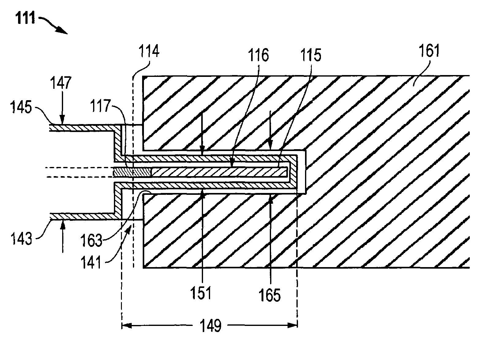
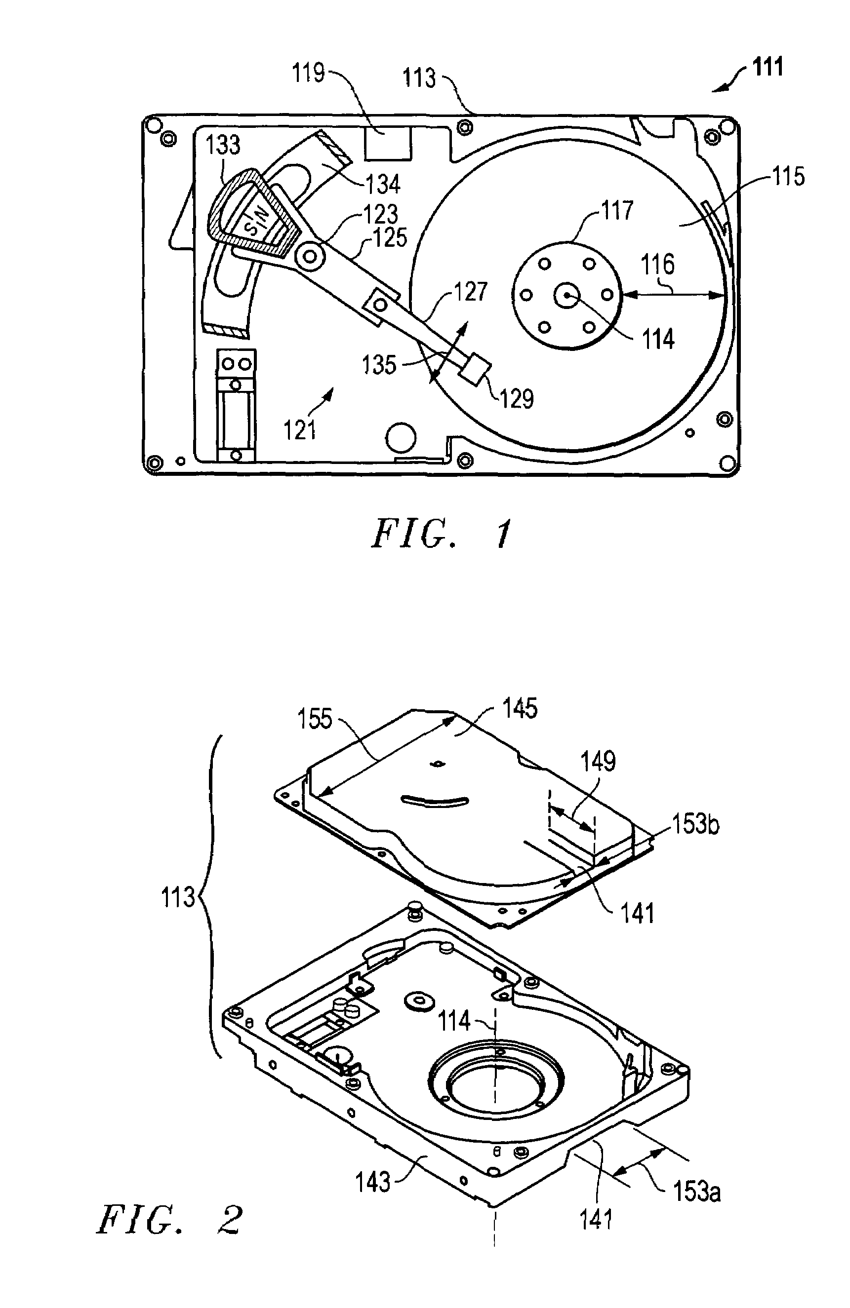
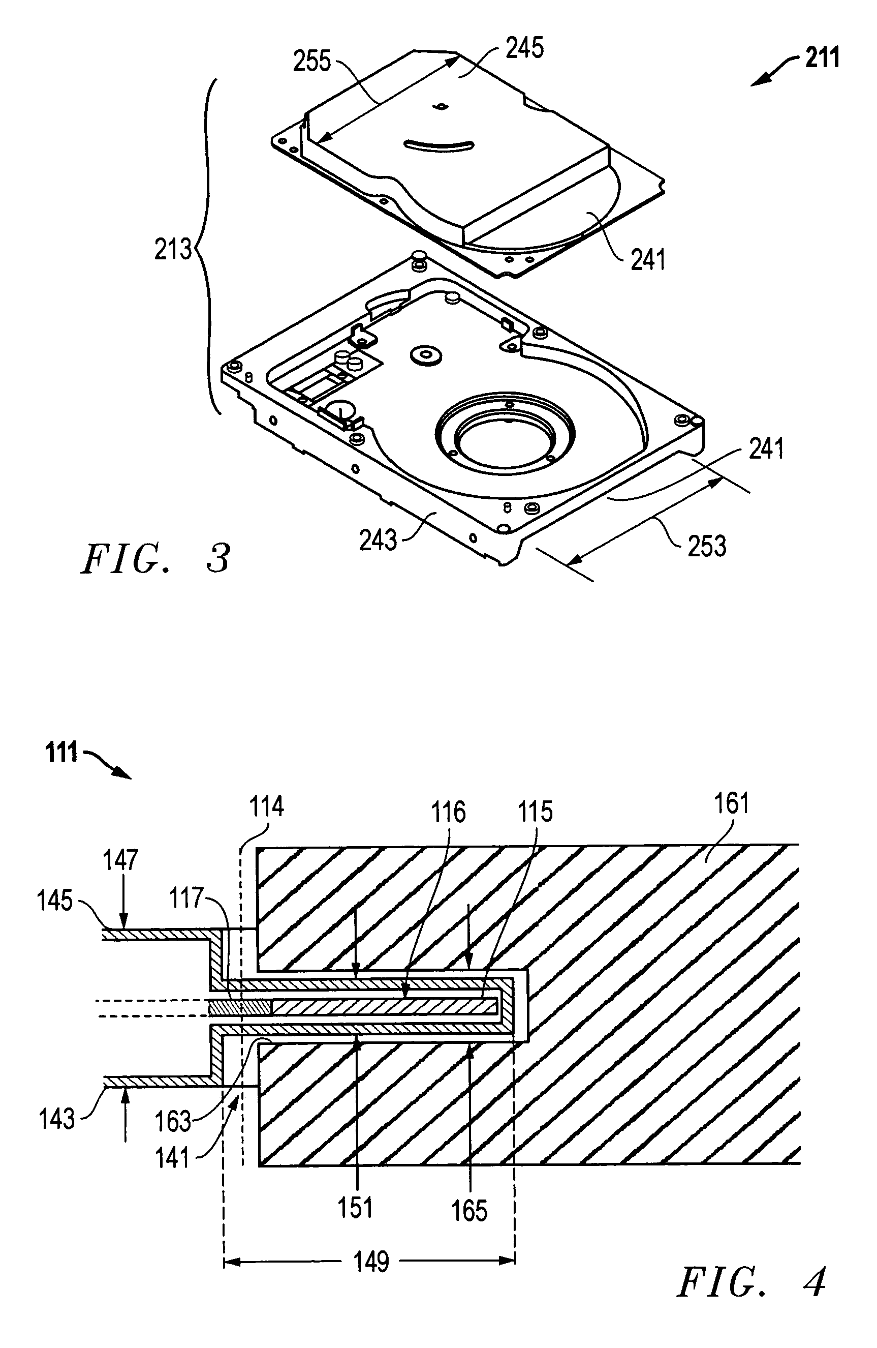
[0032]Referring to FIG. 1, a schematic drawing of one embodiment of an information storage system comprising a magnetic hard disk file or drive 111 for a computer system is shown. Drive 111 has an outer housing or enclosure 113 containing at least one magnetic disk 115. Disk 115 has an axis of rotation 114, a storage area 116, and is rotated by a spindle motor assembly having a central drive hub 117. An actuator 121 comprises a plurality of parallel actuator arms 125 (one shown) in the form of a comb that is pivotally mounted to enclosure 113 about a pivot assembly 123. A controller 119 is also mounted to enclosure 113 for selectively moving the comb of arms 125 relative to disk 115.

[0033]In the embodiment shown, each arm 125 has extending from it at least one cantilevered load beam and suspension 127. A magnetic read / write transducer or head is mounted on a slider 129 and secured to a flexure that is flexibly mounted to each suspension 127. The read / write heads magnetically read da...


PUM

PropertyMeasurementUnit
sizeaaaaaaaaaa
sizeaaaaaaaaaa
axial thicknessaaaaaaaaaa

Abstract

A method of erasing information on one or more disks in a disk drive uses a high strength magnetic field to erase the disks while the disks are in the HDD assembly. The design of the head disk enclosure provides a reduced thickness in a localized region over the disks. This allows a narrower working magnetic gap of the HDD level disk erase apparatus. The localized region of the HDD may be a formed indentation on the top cover, elimination of flange, and reduced floor thickness of the HDD base.

Description

BACKGROUND OF THE INVENTION[0001]1. Technical Field[0002]The present invention relates in general to an improved hard disk drive design and, in particular, to an improved method of erasing or preconditioning the magnetic media of the disk or disks in a hard disk drive at the assembly level.[0003]2. Description of the Related Art[0004]Generally, a data access and storage system consists of one or more storage devices that store data on magnetic storage media. For example, a magnetic storage device is known as a direct access storage device (DASD) or a hard disk drive (HDD) and includes one or more disks, read / write head(s) with actuator and associated controller and electronics to manage local operations concerning the actuator, disks and data stored on the disks. The hard disk(s) themselves are usually made of a substrate of aluminum alloy or a mixture of glass and ceramic, and are covered with a magnetic film coating. The magnetic coating can be several layers of different metal al...

Claims


Application Information

Patent Timeline
Patent Type & Authority Patents(United States)
IPC IPC(8): G11B5/03G11B5/012G11B5/024
CPCG11B5/0245G11B5/012
Inventor PRICE, KIRKSCHIRLE, NEAL BERTRAM
Owner WESTERN DIGITAL TECH INC
Why Eureka
Try Eureka