

Windshield wiper device mounting washer nozzle and hose
- Summary
- Abstract
- Description
- Claims
- Application Information
AI Technical Summary
Benefits of technology
Problems solved by technology
Method used
Image

Examples
first embodiment
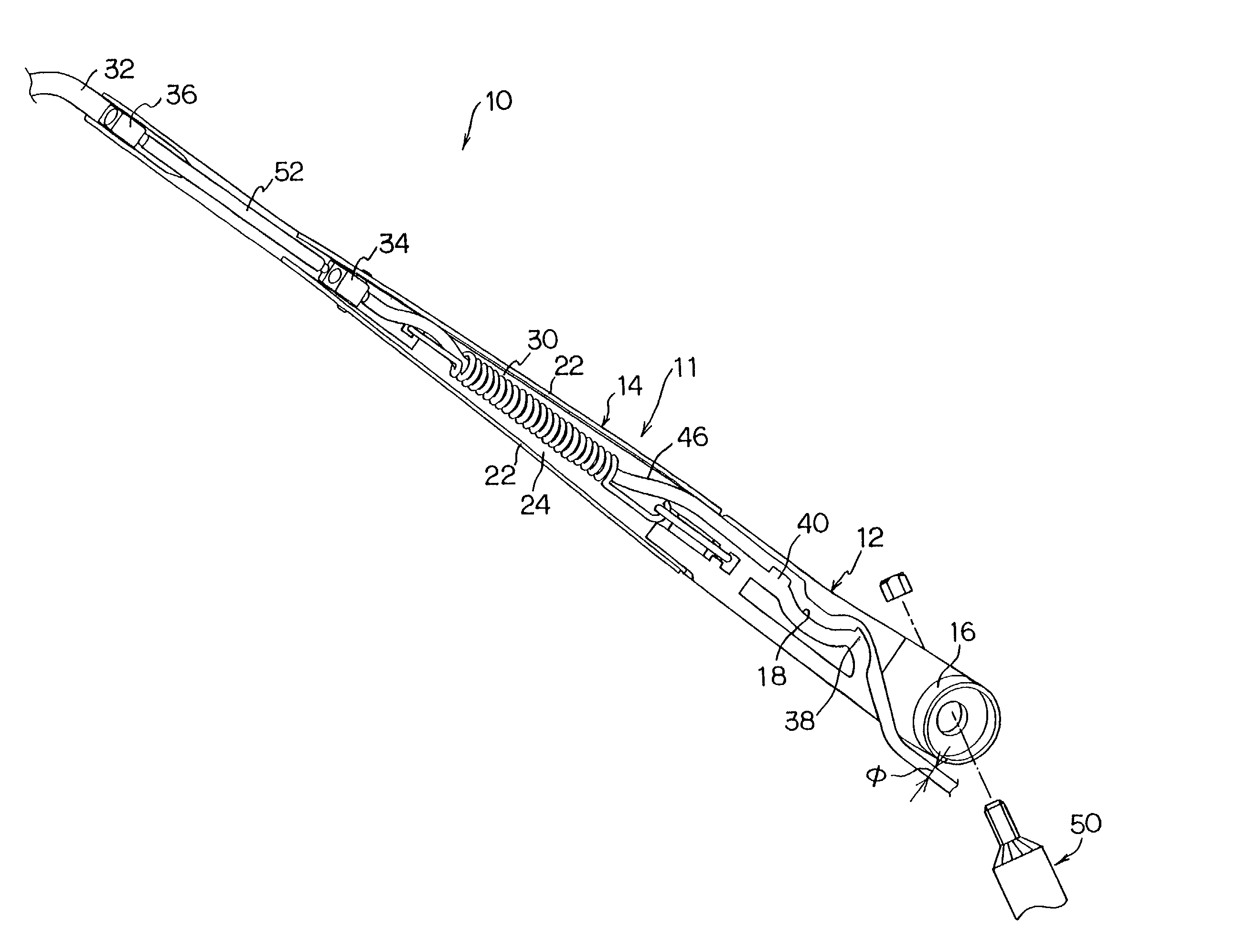
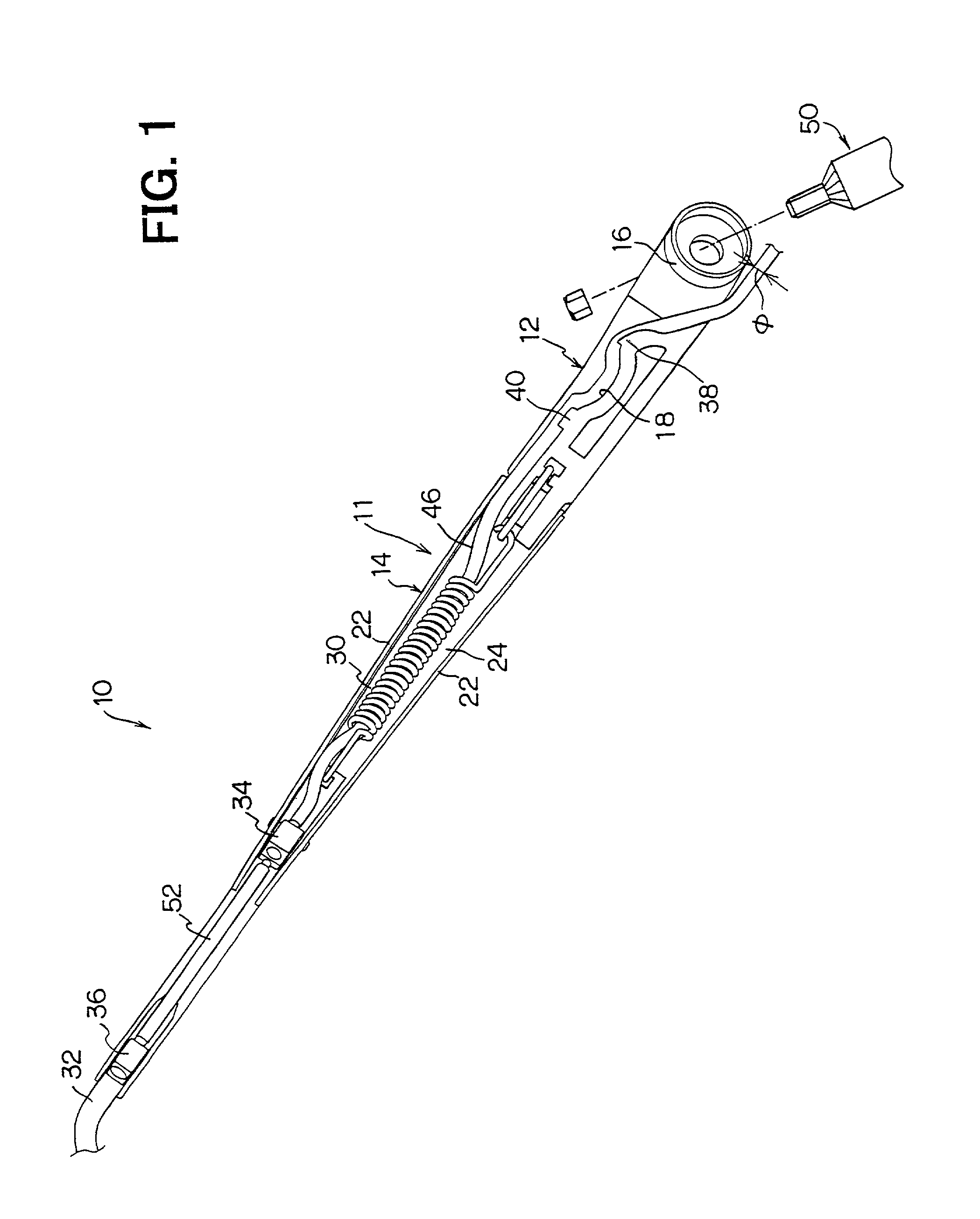
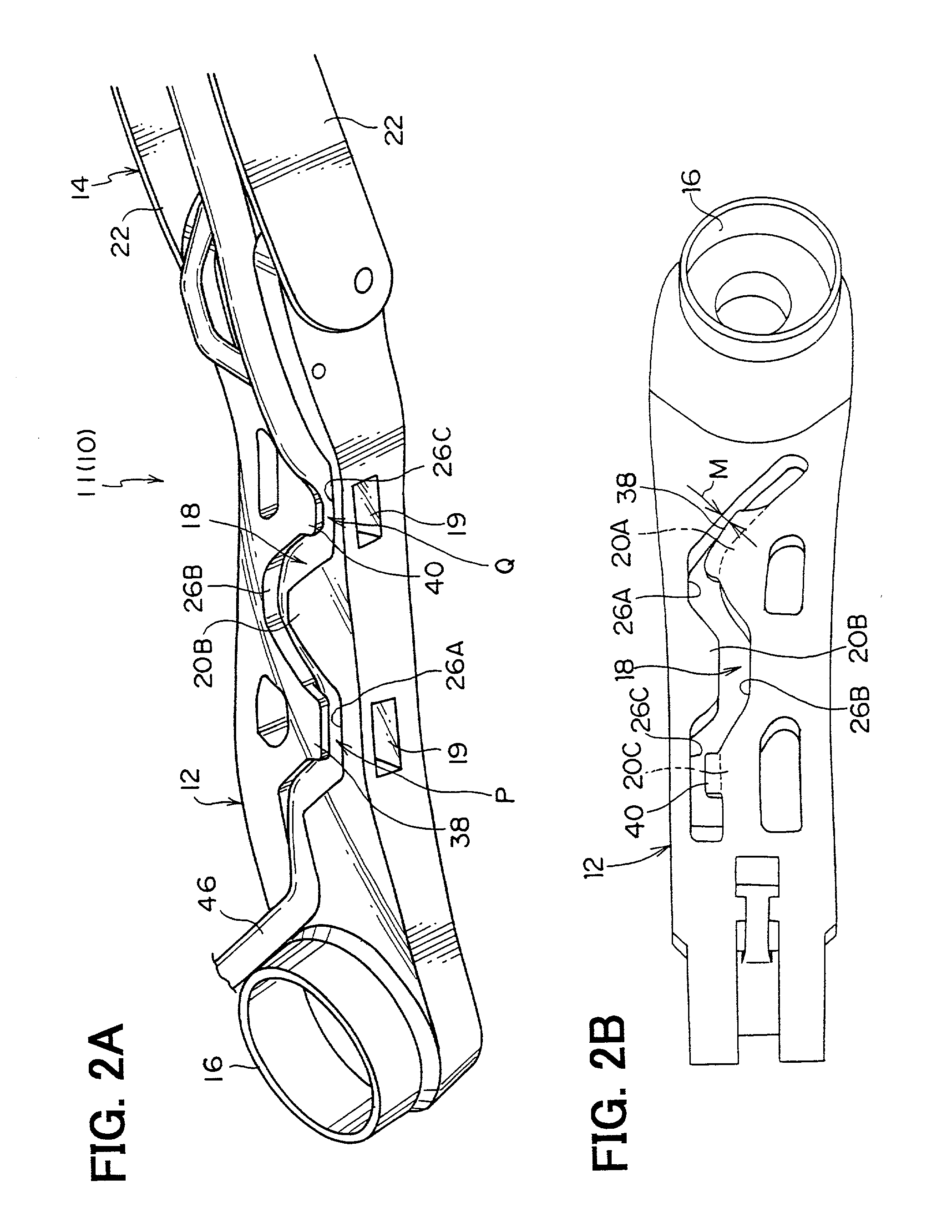
[0039] FIG. 1 shows a backside of a wiper arm constituting a part of a windshield wiper device according to the present invention. FIG. 2A is a perspective view of a backside of an arm head as a part of the wiper arm of FIG. 1. FIG. 2B is a plane view of the arm head of FIG. 2A.
[0040] A windshield wiper device 10 has a wiper arm 11 driven through a pivot shaft 50 by a power source such as wiper motor (not shown) and a wiper blade (not shown) to be attached to the wiper arm 11 for wiping a windshield glass (not shown). Since the power source, the wiper blade and the windshield glass are well known, the structures thereof are not be elaborated for the sake of brevity.
[0041] The wiper arm 11 has an arm head 12, a retainer 14, and an arm piece 32. The retainer 14 and the arm piece 32 constitute an arm element. An end of the arm head 12 is fixed to the pivot shaft 50, which is rotatably attached to a vehicle body, so that the arm head 12 rotate always together with the pivot shaft 50. As...
second embodiment
[0074] A windshield wiper device 70 having an arm head 72 according to a second embodiment is described with reference to FIGS. 7 to 10.
[0075] The arm head 72 is provided on a backside thereof with an elongated and undulated groove 18 and projections 38 and 40, similarly to those of the arm head 12 according to the first embodiment.
[0076] A part of sidewalls constituting the groove 18, which is a portion corresponding to the hill portion 26A or 26C which is opposed to the hill portion 20A or 20C having the projection 38 or 40 in the first embodiment, is completely removed so that a thickness of the arm head 18 on one width side thereof, which is a side from which the slide die 62 is inserted, is thinner than that on the other width side thereof. Accordingly, there is no holes like the holes 19 in the first embodiment, each of which is formed to penetrate one of the side wall of the groove 18 on inserting the slide die 62 into the split die 62 and the cavity 64 to form the groove 18 ...
third embodiment
[0078] A windshield wiper device 80 having an arm head 82 according to a third embodiment is described with reference to FIGS. 11 to 13.
[0079] The arm head 80 is provided with an elongated and undulated groove 18, similarly to that of the first embodiment. The arm head 80 is further provided with plural pairs of projections 84, 86 and 88 which are formed on tops of the hill portions 20A, 20B and 20C and on bottoms of the dale portions 26A, 26B and 26C, respectively. Each pair of projections 84, 86 or 88 extend in a width direction of the groove 18 to overhang the groove 18 and a gap M is formed between free end of the projections 84, 86 or 88. The gap M is narrower than the diameter of the hose 46.
[0080] Since the pair of projections 84, 86 or 88 protrude respectively out of the both sidewalls constituting the groove 18, each length of the projections 84, 86 or 88 in a width direction of the groove 18 is shorter so that each strength of the projections 84, 86 or 88 is stronger, whic...
PUM
| Property | Measurement | Unit |
|---|---|---|
| Length | aaaaa | aaaaa |
| Thickness | aaaaa | aaaaa |
| Diameter | aaaaa | aaaaa |
Abstract
Description
Claims
Application Information