Process for the operation of a gas turbine plant and related gas turbine plant

a gas turbine plant and gas turbine technology, applied in steam engine plants, machines/engines, mechanical equipment, etc., can solve the problems of inability to reduce the emission of co.sub.2, the combustion chamber cannot be fully occupied, and the high pressure level is not permissibl

Inactive Publication Date: 2002-09-26
ANSALDO ENERGIA IP UK LTD
View PDF0 Cites 59 Cited by
  • Summary
  • Abstract
  • Description
  • Claims
  • Application Information

AI Technical Summary

Problems solved by technology

If the combustion process is fed with atmospheric oxygen, the flue gases arising in the combustion remain mixed with atmospheric nitrogen, so that the CO.sub.2 emission problem can however be only marginally reduced, and especially in this case the CO.sub.2 is mixed with nitrogen oxides in the resulting flue gases and can only be isolated from the circuit with greater difficulty.
Such a high pressure level is however not permissible within the combustion chamber, in view of the very high combustion temperatures which prevail there.
A further problem in the operation of the said gas turbine plants is represented by the extremely high heat capacity of highly pressurized CO.sub.2, which likewise rises with increasing pressure conditions.

Method used


Image

  • Process for the operation of a gas turbine plant and related gas turbine plant
  • Process for the operation of a gas turbine plant and related gas turbine plant
  • Process for the operation of a gas turbine plant and related gas turbine plant

Examples


Embodiment Construction

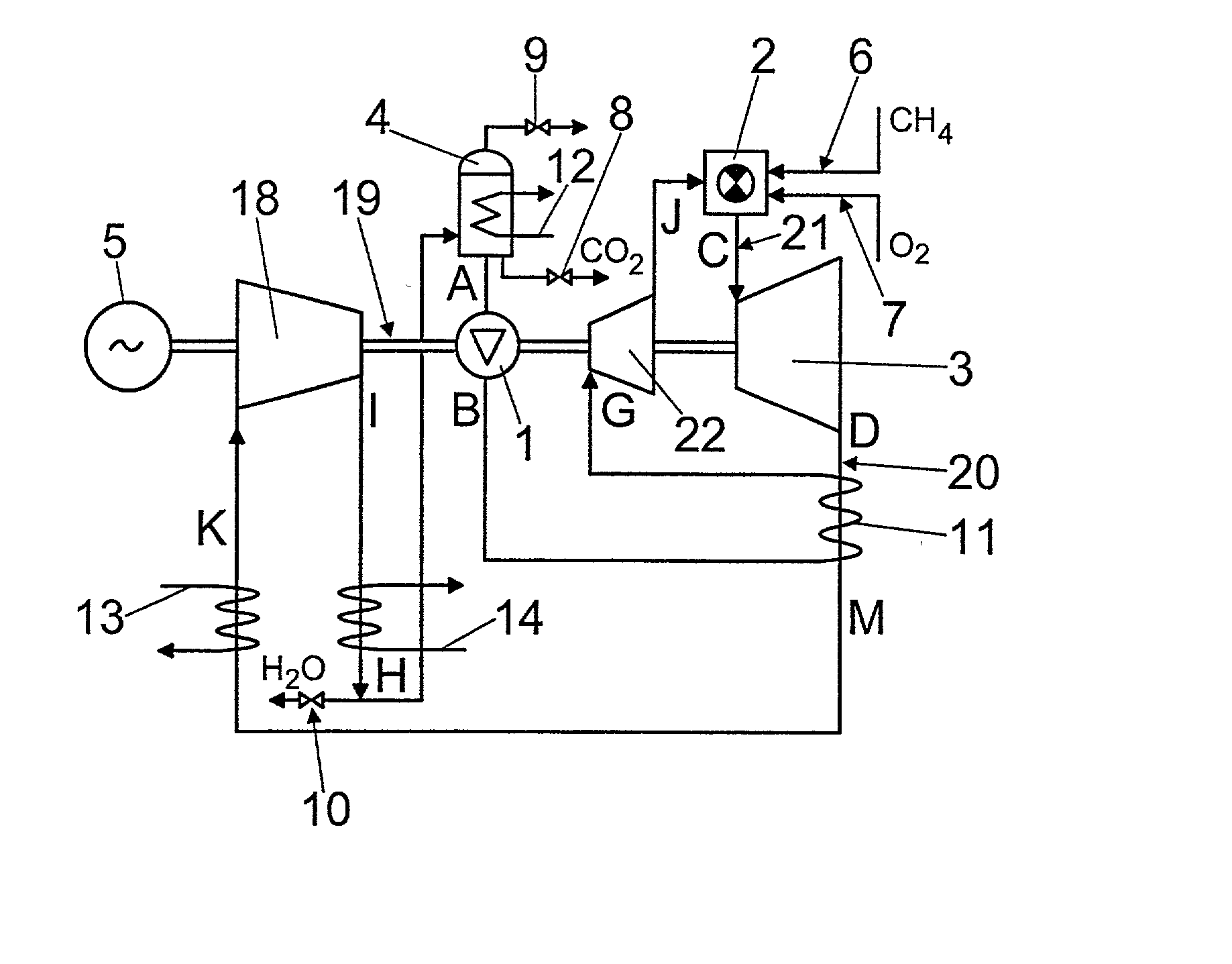
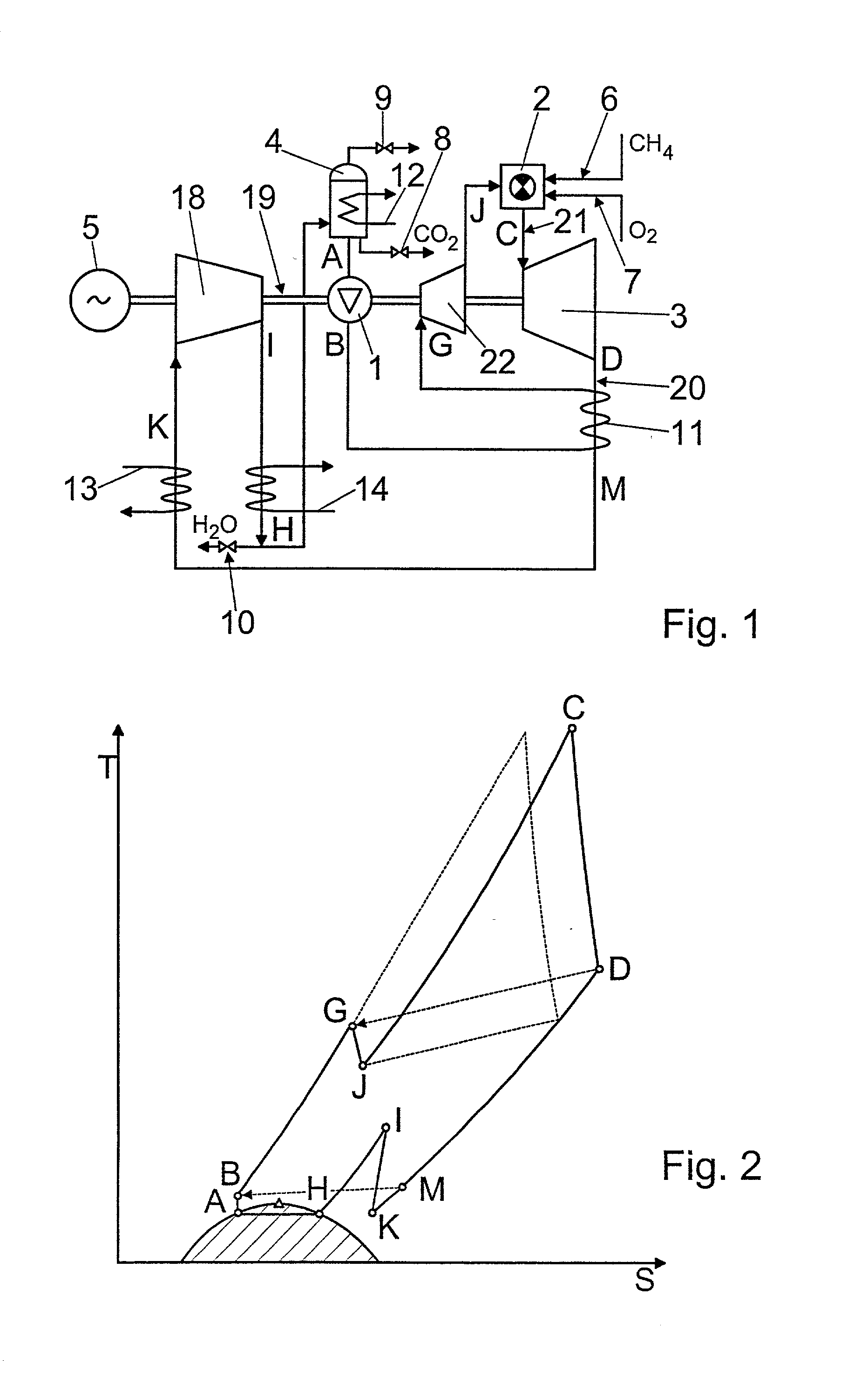
[0019] A schematized circuit diagram of a quasi-closed CO.sub.2 circuit is shown in FIG. 1, and substantially provides for a construction comparably similar to the CO.sub.2 circuit described for the prior art with reference to FIG. 5. In order to avoid repetitions, the reference numerals used in FIG. 1 refer to similarly named components which were already introduced and described with reference to FIG. 5. A new component of the gas turbine plant described in FIG. 1 is the further turbine stage 22, which is inserted into the quasi-closed CO.sub.2 circuit between the pump unit 1 and the combustion chamber 2. The CO.sub.2 gases, compressed to a high pressure, after leaving the pump unit 1 are conducted through a heat exchanger unit 11 in which they are additionally heated by thermal coupling to the hot exhaust gases leaving the turbine stage 3, before they enter the second turbine stage 22 for expansion. The CO.sub.2 gases expanded by the turbine stage 22 then reach the combustion cha...


PUM


Abstract

A process is described for the operation of a gas turbine plant with CO2 as working medium, in which in at least one combustion chamber hydrocarbons are combusted in a CO2 atmosphere enriched with oxygen to flue gases, which largely consist of CO2 and H2O and which are expanded within a turbine stage following the at least one combustion chamber, and are then compressed in a compressor stage and also at least partially condensed in a following condenser, so that at least portions of the CO2 and H2O are liquefied and partially drawn off together with uncondensed flue gas constituents, and so that a main portion, not drawn off, of liquid CO2 is compressed by means of a pump unit, preheated in at least one recuperator stage, and is again supplied to the combustion chamber. The invention is distinguished in that the compressed and preheated main portion CO2 is pre-expanded to a combustion pressure and is supplied to the combustion chamber for combustion with the main portion CO2.

Description

[0001] The invention relates to a process for the operation of a gas turbine plant with CO.sub.2 as the working medium, in which in at least one combustion chamber hydrocarbons are combusted in an oxygen-enriched CO.sub.2 atmosphere to flue gases, which largely consist of CO.sub.2 and H.sub.2O and which are expanded within a turbine stage following the at least one combustion chamber, and are then compressed in a compressor stage and at least partially condensed in a following condenser, so that at least a portion of the CO.sub.2 and H.sub.2O is liquefied and partially drawn off together with uncondensed flue gas components, and so that a main portion, not drawn off, of liquid CO.sub.2 is compressed by means of a pump unit, preheated in at least one recuperator stage, and is again supplied to the combustion chamber.DESCRIPTION OF PRIOR ART[0002] Gas turbine plants with internal combustion and a quasi-closed circuit for CO.sub.2 as working medium represent examples of a very promisin...

Claims


Application Information

Patent Timeline
Patent Type & Authority Applications(United States)
IPC IPC(8): F01K25/10F02C1/10F02C3/20F02C3/30F02C3/34F02C7/08F02C7/143
CPCF01K25/103F02C1/10F02C3/20F02C3/30F02C3/34F02C7/08F02C7/143F05D2210/12
Inventor FRUTSCHI, HANS ULRICH
Owner ANSALDO ENERGIA IP UK LTD
Why Eureka
Try Eureka