In-pipe wastewater treatment system

a wastewater treatment system and in-pipe technology, applied in the direction of filtration separation, liquid displacement, separation process, etc., can solve the problems of deterioration of both materials in sewage, high cost of fibreglass tanks, and easy flotation of plastic tanks

Inactive Publication Date: 2002-09-26
JOWETT E CRAIG
View PDF0 Cites 22 Cited by
  • Summary
  • Abstract
  • Description
  • Claims
  • Application Information

AI Technical Summary

Problems solved by technology

The material has to be watertight, and must remain so for many years, and has to withstand the stresses arising from settling of the ground, from overloading and other abuses, and the like.
However, both these materials deteriorate in sewage, especially where sulphur is present.
However, when the tank is pumped out during service, or if the water table should rise, a tank made of plastic might be prone to flotation.
Fibreglass tanks are very expensive.
Polyethylene tanks are not so durable, and can collapse if not installed and backfilled with unusual skill and care.
Also, the known plastic tanks still take up more or less the same size of hole in the ground, so there is little saving of space, or of amount of excavation.
It has been recognised that, in a case where the water can pass rapidly along a pathway that has developed, from inlet to outlet, the volume of the tank is not being used efficiently.
But baffles are awkward structures to incorporate into a septic tank.
If the baffles really are effective to bring all points of the septic tank into equal effec...

Method used


Image

  • In-pipe wastewater treatment system
  • In-pipe wastewater treatment system
  • In-pipe wastewater treatment system

Examples


Embodiment Construction

[0010] By way of further explanation of the first aspect of the invention, exemplary embodiments of the invention will now be described with reference to the accompanying drawings, in which:

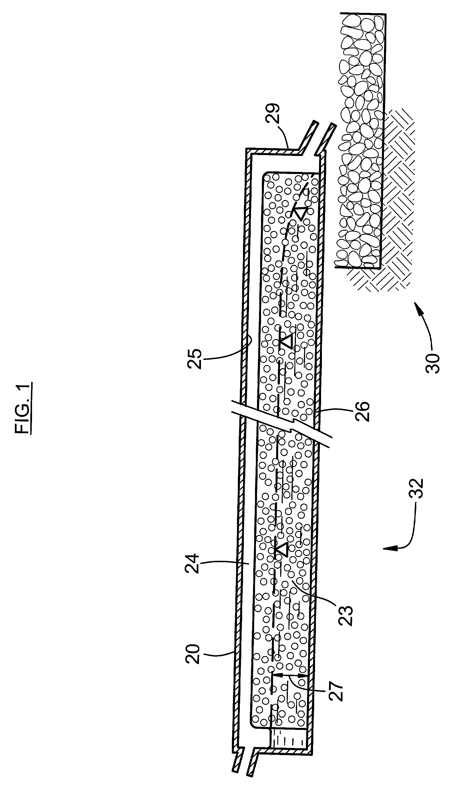
[0011] FIG. 1 is a diagrammatic cross-sectioned side view of a system for treating wastewater that embodies the invention.

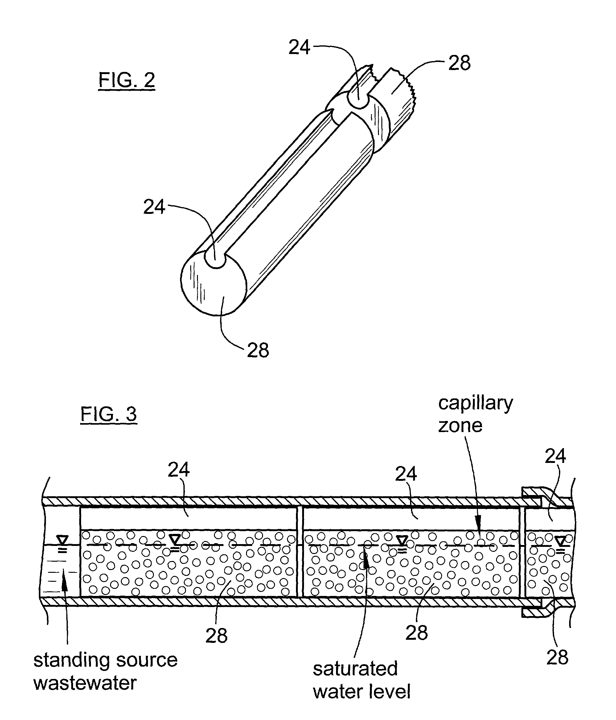
[0012] FIG. 2 is a pictorial view of a body of foam material, which is a component of the system of FIG. 1.

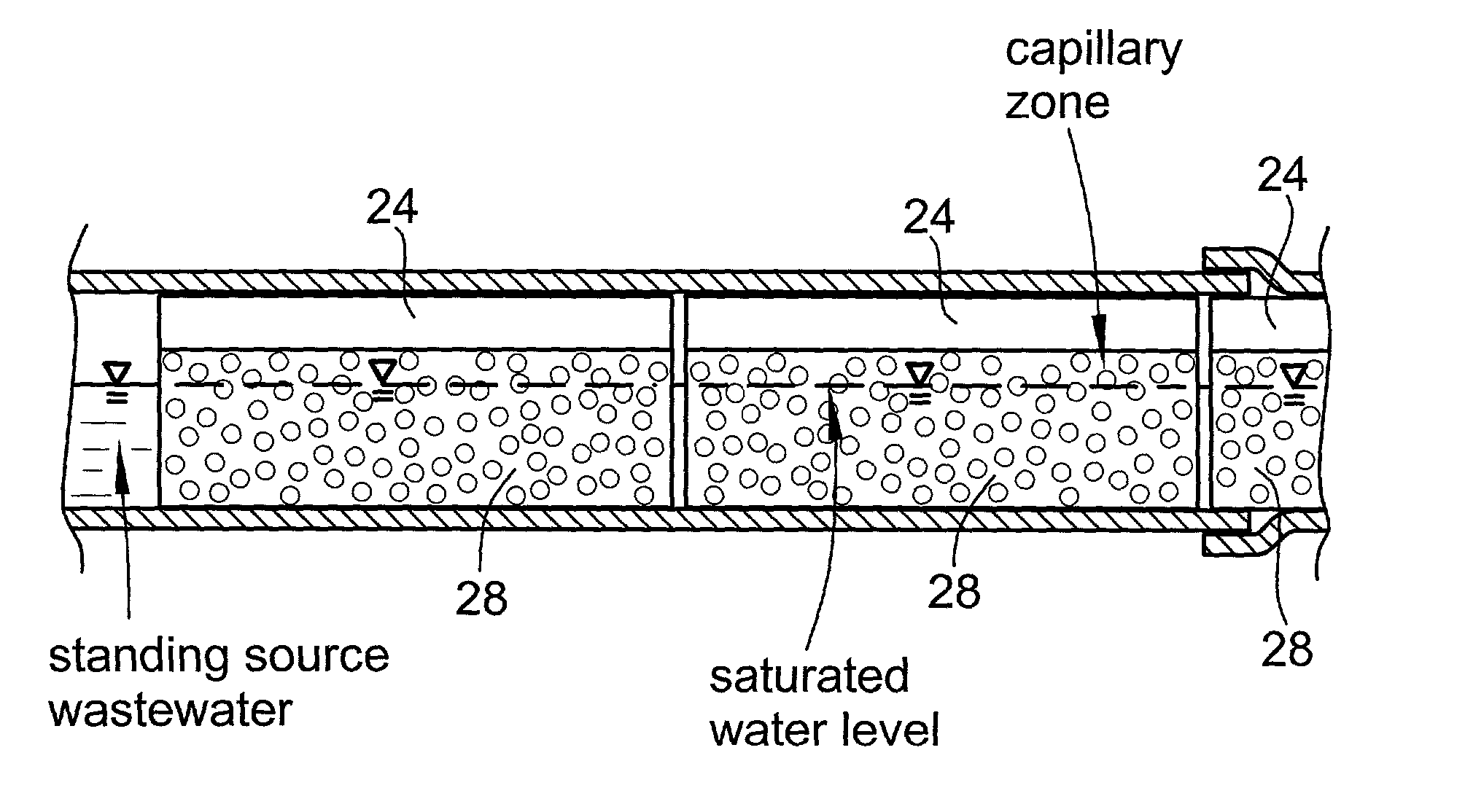
[0013] FIG. 3 is a close-up of a portion of FIG. 1.

[0014] FIG. 4 is a plan view of the treatment system of FIG. 1.

[0015] FIG. 5a is a diagrammatic cross-sectioned view of a pipe containing a body of treatment material.

[0016] FIG. 5b is the same view as FIG. 5a, but shows a different condition.

[0017] FIGS. 6a,6b correspond to FIGS. 5a,5b, but show a different treatment material.

[0018] FIG. 7 is an end view of another system for treating wastewater that embodies the invention.

[0019] FIG. 8 is a cross-sectioned side-view of the system of FIG. 7.

[0020] FIG. 9 is an end view, ...


PUM

PropertyMeasurementUnit
Lengthaaaaaaaaaa
Lengthaaaaaaaaaa
Lengthaaaaaaaaaa

Abstract

In place of the conventional aerobic treatment station, wastewater undergoes aeration in a treatment-pipe. The treatment-pipe has a long/narrow configuration. Open-cell foam serves as treatment material, in the treatment pipe, and promotes attachment of microbial colonies. Two or more treatment-pipes may be connected in series or parallel. Also, in place of a conventional septic tank, wastewater undergoes anaerobic treatment and settlement in a treatment-pipe. The treatment-pipe has a long/narrow configuration. End chambers provide inlet and outlet ports, a sump for collecting settled-out solids, and sealing attachments for the treatment-pipe itself.

Description

[0001] In a first aspect, this invention relates to typically aerobic, microbial treatment of mainly domestic sewage and other wastewaters, and to the renovation of polluted water in general.THE FIRST ASPECT OF THE INVENTION, IN RELATION TO THE PRIOR ART[0002] One common arrangement for treating wastewater has the following elements or stations: (a) an anaerobic digester station; (b) an aeration station; and (c) an infiltration station. In that case, the first aspect of the invention may preferably be utilised in the aeration station.[0003] Water entering an aeration station may be water that has just emerged from a septic tank. Here, solid materials in the wastewater can settle out, and reductive breakdown reactions can take place, which break down much of the organic content of the wastewater, both solid and dissolved. Dissolved ammonium in the water is largely not affected by passage through the septic tank. Water emerging from a well-engineered septic tank has only a small undis...

Claims


Application Information

Patent Timeline
IPC IPC(8): C02F3/06C02F3/10C02F3/12C02F3/28
CPCC02F3/06C02F3/10C02F3/2806C02F2307/08Y02W10/10
Inventor JOWETT, E. CRAIG
Owner JOWETT E CRAIG
Why Eureka
Try Eureka